Inertia type fluid transportation and pressurization method and device

An inertial, fluid output port technology, applied in the direction of machines/engines, mechanical equipment, pumps, etc., can solve the problem of large power consumption, achieve low power consumption and improve energy saving effects

Inactive Publication Date: 2017-08-01
吕夏春
View PDF0 Cites 2 Cited by
  • Summary
  • Abstract
  • Description
  • Claims
  • Application Information

AI Technical Summary

Problems solved by technology

[0003] The purpose of the present invention is to overcome the defect of large power consumption when the existing water pump or air pump compresses the

Method used


Image

  • Inertia type fluid transportation and pressurization method and device
  • Inertia type fluid transportation and pressurization method and device

Examples


Example Embodiment

[0018] Implementation mode one

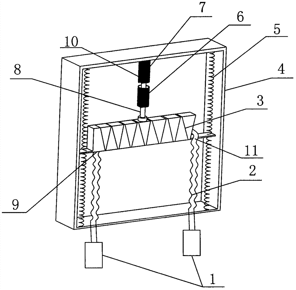
[0019] The present invention uses a plurality of containers 3 to be connected in series in series. Each container 3 contains fluid, especially gas. The container 3 is provided with two through holes separated by a distance as the fluid input port and the fluid output port. The fluid input port and The fluid output ports are equipped with one-way valves to control the one-way input and output flow of the fluid. The fluid input port on the latter container 3 is connected with the fluid output port on the previous container 3, and the vibration drive mechanism is used to drive the container 3 to vibrate to make the container 3 The direction of fluid movement in the cavity changes alternately. Through the squeezing of the fluid under the action of inertia and the one-way control of the fluid flow direction by the one-way valve, the fluid in the container will circulate through each container in turn during the vibration process. Step-by-step pressuriz...

Example Embodiment

[0021] Implementation mode two

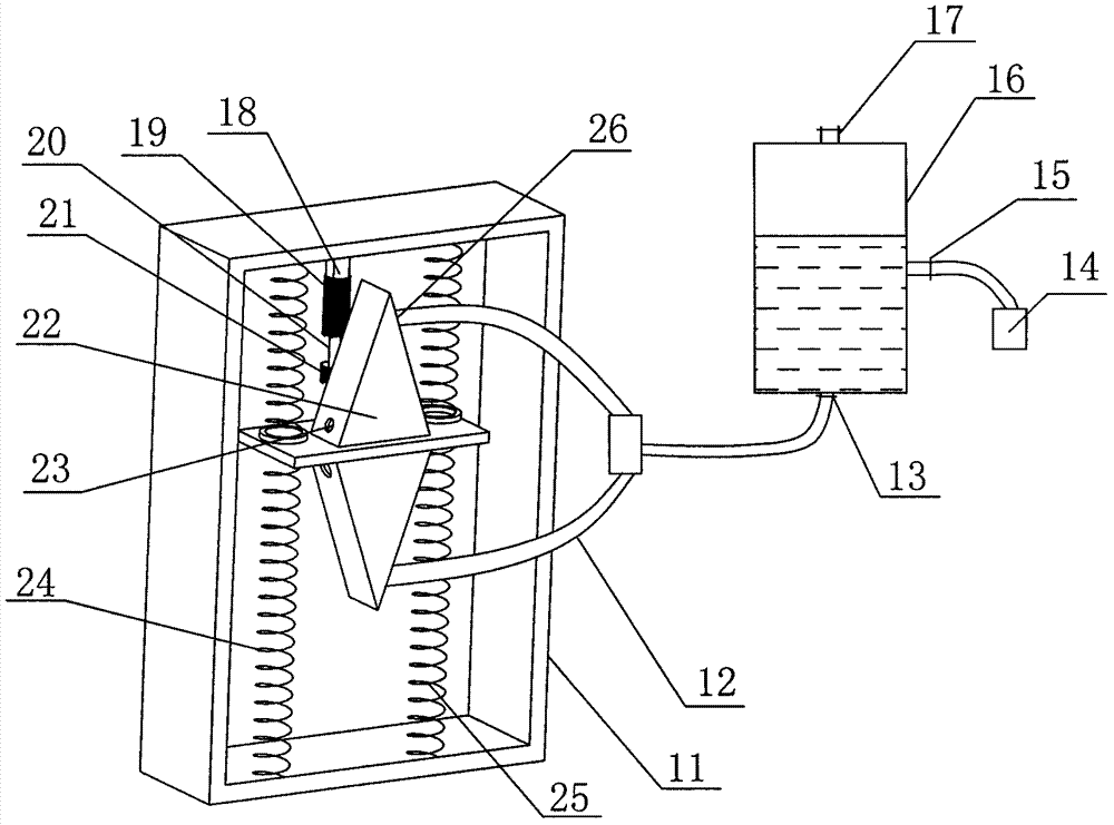
[0022] The present invention uses a plurality of mutually independent containers 22 to be fixedly connected in parallel. Each container 22 contains fluid, especially liquid. The container 22 is provided with two through holes spaced apart as the fluid input port 23 and the fluid output port 26. Both the fluid input port 23 and the fluid output port 26 are provided with a one-way valve to control the one-way input and output flow of the fluid, and a vibration drive mechanism is used to drive the container to reciprocate and vibrate. Each container 22 is arranged side by side in the direction of vibration. The upper fluid output ports 26 are connected to each other through pipes, and output from the fluid output ports 26 of each container and output after converging through the connected pipes. During the vibration of the container, the fluid movement direction in the container alternately changes, which is generated by the fluid under the action of ...


PUM


Abstract

The invention discloses an inertia type fluid transportation and pressurization method and device and belongs to the technical field of fluid transportation and pressurization. A container is used for containing fluid, two through holes are formed in the container in a spaced mode to be used as a fluid input port and a fluid output port, and the fluid input port and the fluid output port are provided with one-way valves for controlling one-way input and output flow of fluid correspondingly. A vibration driving mechanism is used for driving the container to vibrate, the movement direction of fluid in an inner cavity of the container is alternately changed, and transportation and pressurization for fluid are achieved through extrusion produced to fluid under the inertia effect and one-way control of the one-way valves on the flow direction of fluid. Transportation and pressurization for fluid are achieved, the vibration driving mechanism can maintain reciprocating vibration of the container only through minute electric energy in the working process, electric energy consumption is low, and the energy saving effect is greatly improved.

Description

technical field [0001] The invention belongs to the technical field of fluid delivery and pressurization, and in particular relates to an inertial fluid delivery and pressurization method and a device thereof. Background technique [0002] Common water pumps and air pumps have two principles for compressing fluids such as liquids or gases. One is a positive displacement pump, which reciprocates through the piston. In this way, the piston and the pump body need to be in direct contact and sealed, and the friction is relatively large. The other is the vane pump, which is pressurized through the rotation of the vane, but there is a strong relative motion between the vane and the fluid, while the water pump and the air pump are usually driven by electric energy, so the power consumption is large, and there is a large energy consumption and cost. higher. Contents of the invention [0003] The object of the present invention is to overcome the defect of large power consumption ...

Claims


Application Information

Patent Timeline
IPC IPC(8): F04F7/00
CPCF04F7/00
Inventor 吕夏春
Owner 吕夏春
Why Eureka
Try Eureka