Supercharge Your Innovation With Domain-Expert AI Agents!

Method and system for fault detection in a compressed-air system

A compressed air and fault technology, applied in the field of identifying faults in compressed air systems, can solve expensive and other problems and achieve the effect of improving accuracy

Active Publication Date: 2017-08-01
KNORR-BREMSE SYST FUER NUTZFAHRZEUGE GMBH
View PDF7 Cites 3 Cited by
  • Summary
  • Abstract
  • Description
  • Claims
  • Application Information

AI Technical Summary

Problems solved by technology

The disadvantage of this type of diagnosis is that relatively expensive additional electronic sensing devices are required

Method used


Image

  • Method and system for fault detection in a compressed-air system
  • Method and system for fault detection in a compressed-air system

Examples


Embodiment Construction

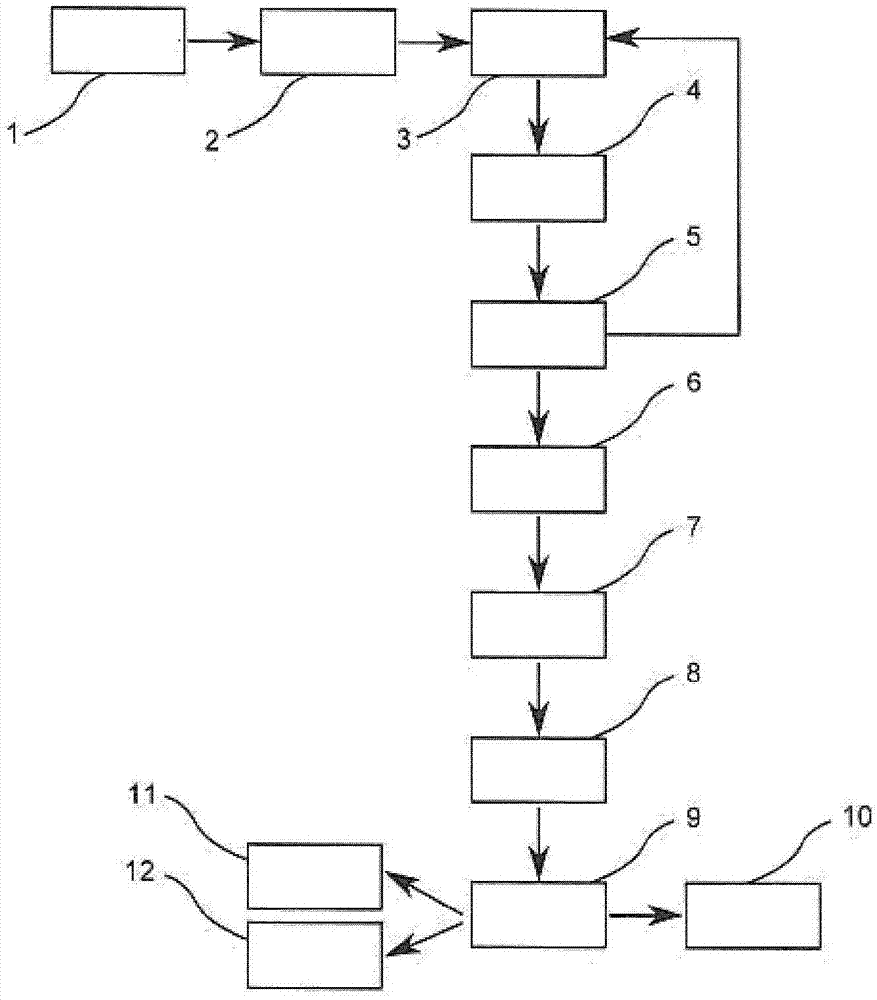
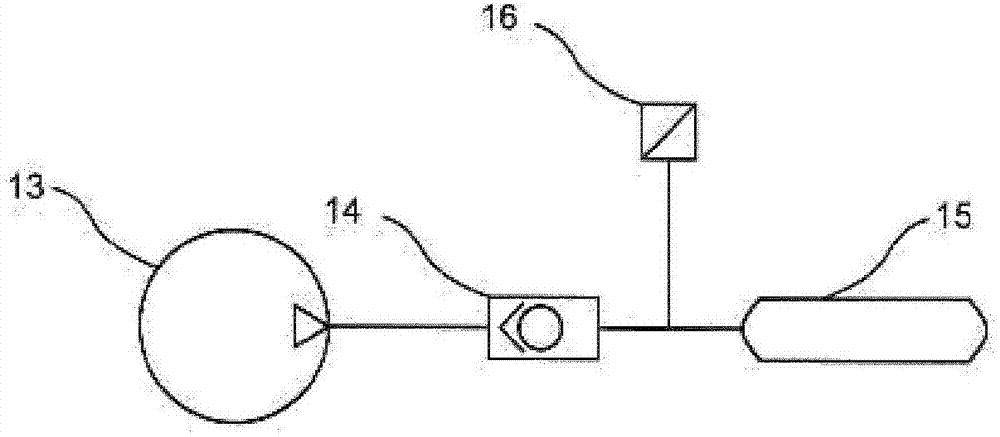
[0032] according to figure 1 , in order to detect a fault in the compressed air system, in a first step 1 the compressed air is measured on the output side of the compressor 13 and stored as a first basic value. The relevant point in time is determined by simultaneously detecting and storing the first time stamp. In the following second step 2, the compressor 13 is activated for generating compressed air. In a third step 3 which follows immediately or at intervals in time, the compressed air is measured again and stored as a comparison value. In a fourth step 4 , a value difference between the comparison value and the base value is generated and compared in a value comparison step 5 with a threshold value.

[0033] If the value difference is smaller than the critical value, the method is repeated from the third step 3 onwards. Otherwise, in a sixth step 6, the second time stamp is detected and the time interval from said first time stamp is calculated. In a time comparison...


PUM


Abstract

The invention relates to a method for detecting a malfunction of a compressed-air system, wherein a state variable is measured and is stored as a first base value and a first time stamp is captured and stored in a first step (1), the compressor (13) is activated in a second step (2), the state variable is measured and is stored as a comparison value in a third step (3), the value difference between the comparison value and the base value is formed in a fourth step (4), the value difference is compared with a threshold value in a value comparison step (5), a second time stamp is captured and the time interval with respect to the first time stamp is calculated in a sixth step (6) if the value difference is greater than or equal to the threshold value, the deviation of the time interval from a time interval reference value is determined in a time comparison step (7), and, if the deviation is outside of a tolerance interval, a malfunction is associated with the deviation in a diagnosis step (8).

Description

technical field [0001] The invention relates to a method for detecting faults in a compressed air system. Furthermore, the invention relates to a compressed air system, preferably in a motor vehicle, comprising a compressor for generating compressed air, a compressed air reservoir for storing compressed air, preferably comprising A dryer medium for drying the air flowing through is arranged between the compressor and the compressed air reservoir and includes controls for controlling the compressor and for regenerating or drying the dryer medium unit, the compressor is used to generate compressed air. Background technique [0002] The field of use of the invention relates to compressed air systems, in particular those of motor vehicles, in which a compressor, for example a piston compressor, is installed in order to draw in ambient air and supply it, for example, to a compressed air reservoir From the compressed air reservoir, the compressed air can be used, for example, to...

Claims


Application Information

Patent Timeline
Patent Type & Authority Applications(China)
IPC IPC(8): B60T13/26B60T17/22F15B19/00
CPCB60T13/26B60T17/22F15B19/005F15B2211/20538F15B2211/30505F15B2211/6309F15B2211/87F15B2211/8855
Inventor M·克拉博特G·维格O·乌德沃尔迪
Owner KNORR-BREMSE SYST FUER NUTZFAHRZEUGE GMBH
Features
  • R&D
  • Intellectual Property
  • Life Sciences
  • Materials
  • Tech Scout
  • Unparalleled Data Quality
  • Higher Quality Content
  • 60% Fewer Hallucinations
Learn More