Controllable shock absorber for motor vehicles

A shock absorber, vehicle technology, applied in the direction of shock absorber, spring/shock absorber, shock absorber, etc., can solve the problems of small inflow section of hydraulic pipeline and inability to maintain pressure, etc.

Active Publication Date: 2017-08-01
THYSSENKRUPP AG +1
View PDF10 Cites 3 Cited by
  • Summary
  • Abstract
  • Description
  • Claims
  • Application Information

AI Technical Summary

Problems solved by technology

Under dynamic conditions, the pressure in some seat areas cannot be maintained due to the relatively small inflow cross-section of the associated hydraulic lines

Method used


Image

  • Controllable shock absorber for motor vehicles
  • Controllable shock absorber for motor vehicles
  • Controllable shock absorber for motor vehicles

Examples


Embodiment Construction

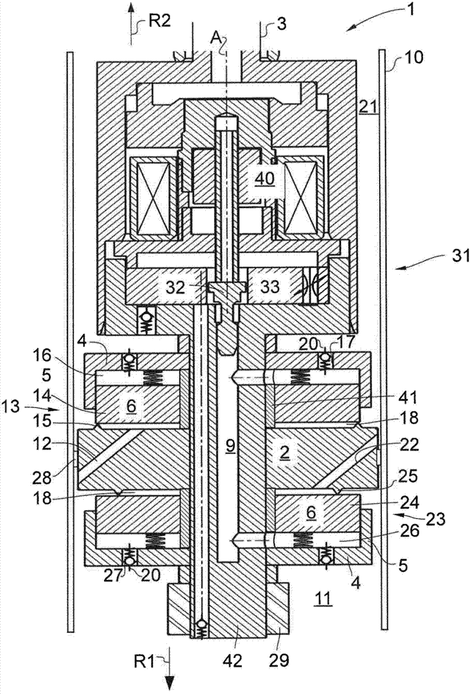
[0029] figure 1 A detail of a conventional shock absorber 1 as described in the not yet published German patent application 102013114169.2 is shown.

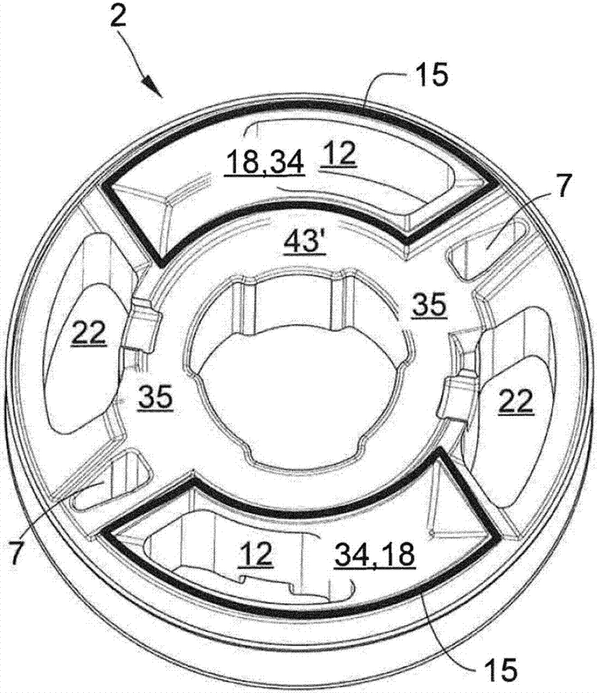
[0030] The shock absorber 1 comprises a cylinder 10 in which a piston 2 is held so as to be displaceable along a cylinder axis A. As shown in FIG. The piston 2 comprises an annular seal 28 on its outer circumference, so that the piston 2 seals the cylinder 10 into a first (piston rod facing away) working chamber 11 and a second (piston rod facing) working chamber 21 . The piston 2 is fastened to a fastening journal 42 which in turn is fixedly connected to the piston rod 3 . In case of actuation of the piston rod 3 in the first actuation direction R1 towards the first working chamber 11 (also called "compression direction"), the pressure in the first working chamber 11 increases. The fluid present in the first working chamber 11 then flows into the second working chamber 21 through the first fluid passage 12 in the piston 2 . ...


PUM


Abstract

The invention relates to a controllable shock absorber, in particular for a vehicle suspension. The shock absorber comprises a cylinder pipe with a hydraulic fluid sealed therein, a piston (2), which can be moved axially inside the cylinder pipe along a cylinder pipe axis and which sub-divides the cylinder pipe into two working chambers, and a piston rod running parallel to the cylinder pipe axis and connected to the piston (2). The piston (2) has at least two fluid passages (12, 22), by means of which one working chamber is connected to the other working chamber, and a first valve arrangement is located at a first fluid passage (12) in order to damp the movement of the piston in a first actuation direction and a second valve arrangement is located at a second fluid passage (22) in order to damp the movement of the piston in a second actuation direction. In the piston (2), in addition to the fluid passages (12, 22) a bypass channel (7) having flow cross-sections of differing sizes for the two flow directions is provided, or multiple bypass channels (7) are provided, the sum of the flow cross-sections of said multiple channels differing in size for the two flow directions. By means of the single bypass channel (7) one fluid connection is formed between the two working chambers, bypassing the pre-chambers, or by means of the multiple bypass channels (7) multiple fluid connections are formed between the two working chambers, bypassing the pre-chambers.

Description

technical field [0001] The invention relates to an adjustable shock absorber according to the preamble of claim 1 . Background technique [0002] A shock absorber of this type is known from DE 44 41 047 C1. A pressure-dependent damping valve is arranged on the axially guided piston within the cylinder for fluid exchange between the two working chambers during the rebound phase and the compression phase. The pilot controller acts such that a controlled pressure builds up in the pilot control chamber. Pilot control pressure forces the orifice valve disc into the orifice valve closed position. Fluid is led out of the working chamber into the pilot control chamber by means of the bypass line system, thus increasing the pressure at the pilot control chamber. The pilot control pressure is controlled by means of an externally adjustable pilot control valve arranged in the bypass line system. The elastic element forms a partition between the pilot control chamber and the working...

Claims


Application Information

Patent Timeline
Patent Type & Authority Applications(China)
IPC IPC(8): F16F9/348
CPCF16F9/348F16F9/3482F16F9/516B62D21/11F16F9/446
Inventor 沃尔夫冈·哈梅尔斯德米特里·斯梅连斯基
Owner THYSSENKRUPP AG
Why Eureka
Try Eureka