Method and apparatus for increasing angular resolution in an automotive radar system

A technology of automotive radar and azimuth, used in radio wave measurement systems, utilization of re-radiation, reflection/re-radiation of radio waves, etc.

Inactive Publication Date: 2017-08-01
VALEO RADAR SYST
View PDF9 Cites 1 Cited by
  • Summary
  • Abstract
  • Description
  • Claims
  • Application Information

AI Technical Summary

Problems solved by technology

This is due to cost considerations and size constraints
This limitation in the antenna leads to problems with the quality of the antenna and the interaction of the antenna with the body of the vehicle on which the automotive radar system is mounted

Method used


Image

  • Method and apparatus for increasing angular resolution in an automotive radar system
  • Method and apparatus for increasing angular resolution in an automotive radar system
  • Method and apparatus for increasing angular resolution in an automotive radar system

Examples


Embodiment Construction

[0032] Described herein are automotive radar systems (also sometimes referred to herein as automotive sensor systems) and techniques suitable for providing unambiguous phase information for locating objects. The techniques described herein are applicable to frequency modulated continuous wave (FMCW) automotive radar systems, however, it should be understood that the systems and techniques described herein may also be used in non-FMCW automotive radars and radars that are not automotive radars.

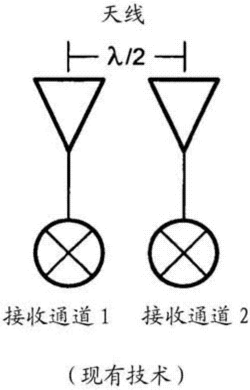
[0033] now refer to figure 2 , the automotive radar system 20 utilizing a three-channel switch antenna to improve the angular resolution of the azimuth tracking dual-channel automotive radar system includes a first antenna 22 and a third antenna 26 separated by a distance of λ / 2 from a second antenna 24, the third antenna 26 The antenna is spaced at a distance of λ from the second antenna 24 and at a distance of 3λ / 2 from the first antenna. The first antenna 22 is coupled to a first ...


PUM


Abstract

Described herein is an automotive radar system and related processing techniques utilizing a three channel switched antenna to improve the angular resolution of an azimuth tracking radar.

Description

technical field [0001] The concepts, systems, circuits, devices and techniques described herein relate generally to radio frequency (RF) circuits, and more specifically to automotive radar systems. Background technique [0002] As is known in the art, some existing automotive radar systems detect targets that generate radar return signals having a signal strength that exceeds a threshold signal strength in range / Doppler space. The radar then makes an estimate of the X-Y position and velocity of each target. This approach typically requires an algorithm in the form of a state machine and tracked with thresholds and heuristics. [0003] refer to Figure 1-1A , some traditional automotive radar systems use two antennas, each feeding one channel of a dual-channel receiver. Such as Figure 1A As shown, the phase difference between the signals in the two channels provides angular information, which can be used to detect targets in the azimuth plane. Theoretically, an antenna s...

Claims


Application Information

Patent Timeline
Patent Type & Authority Applications(China)
IPC IPC(8): G01S7/03G01S7/35G01S13/44G01S13/93G01S13/931
CPCG01S7/03G01S7/352G01S13/4454G01S13/931G01S13/345G01S7/02G01S13/02
Inventor J.米勒J.S.普莱瓦
Owner VALEO RADAR SYST
Why Eureka
Try Eureka