Adjusting members for mechanical watch movements

A technology for adjusting components and watch movements, applied to mechanically driven clocks, clocks, escapement mechanisms, etc., to achieve the effects of reduced demand, small footprint, good stability and operating accuracy

Active Publication Date: 2019-12-20
RICHEMONT INT
View PDF8 Cites 0 Cited by
  • Summary
  • Abstract
  • Description
  • Claims
  • Application Information

AI Technical Summary

Problems solved by technology

On the other hand, the number of parts and their adjustment make the implementation of this system very fine

Method used


Image

  • Adjusting members for mechanical watch movements
  • Adjusting members for mechanical watch movements
  • Adjusting members for mechanical watch movements

Examples


Embodiment Construction

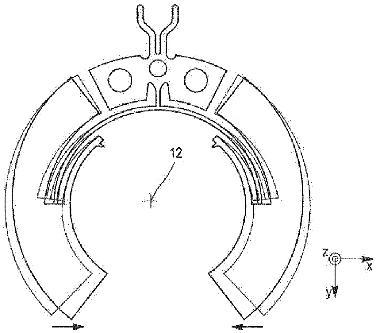
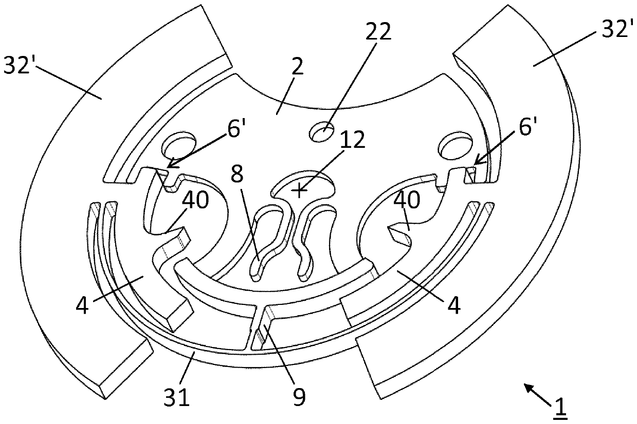
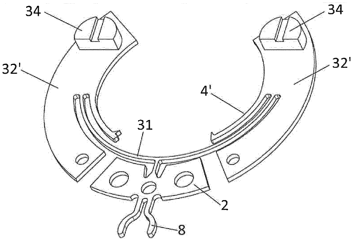
[0069] According to the invention, the adjustment element comprises an escape wheel and a vibrating oscillator (or resonator) comprising at least two vibrating arms coupled in one piece with the pallet part. In particular, each oscillating arm of the vibrating oscillator bears a member, such as a lever (in other words, a pawl), adapted to cooperate with the teeth of the escape wheel. In this way the escape wheel can advantageously be placed between the vibrating arm of the vibrating resonator and the pallet part.

[0070]figure 1 and figure 2 A top view of an adjustment member 1 according to a preferred embodiment of the invention is shown. Here, regulating member 1 comprises an escape wheel 5 and a vibrating oscillator 3 comprising two arms each comprising a vibrating element 31 ′, such as a vibrating reed, and a mass element 32 . In this embodiment, the vibrating element 31' of each arm is part of a single vibrating element 31 forming a tuning fork, and the regulating mem...


PUM


Abstract

The regulating member (1) of a mechanical timepiece movement comprises an escape wheel (5) and a vibrating oscillator (3) provided with at least two vibrating arms (31', 32') and firmly connected to said The vibrating arm also comprises two members (4, 4') arranged to cooperate directly with the teeth of the escape wheel (5), thereby maintaining the periodic alternation of the vibrating oscillator (3) and making the escape wheel (5) The sub-oscillations advance alternately.

Description

technical field [0001] The present invention relates to a regulating or oscillating member for a mechanical timepiece movement, comprising an escape wheel and a vibrating oscillator, in other words a resonator comprising at least two oscillating members or arms, for example reeds of the tuning fork type, and intended to be used with The pallet fork (ancre) part that matches the escape wheel. The invention also relates to a timepiece movement comprising such an adjusting member. This regulating member is intended to replace the conventional regulating member which usually includes a balance-spiral and associated escapement. Background technique [0002] In a timepiece movement, the function of the escapement is to transmit the energy received by the gear train to the regulating member formed by the balance with sprung, the escapement itself is driven by the mainspring. This escapement usually consists of a separate pallet oscillating about an axis pivoting in the dial. The...

Claims


Application Information

Patent Timeline
Patent Type & Authority Patents(China)
IPC IPC(8): G04B15/14G04B17/04G04B17/06
CPCG04B15/14G04B17/04G04B17/06G04B17/063G04B17/045
Inventor O.卡伦E.克莱恩A.赫劳德J.祖彻尔
Owner RICHEMONT INT
Why Eureka
Try Eureka