Method for producing a transmission shaft

A transmission shaft and transmission technology, which is applied to engine components, mechanical equipment, metal processing equipment, etc., can solve the problems of transmission damage, expensive transmission shaft manufacturing, etc., and achieve reduced space requirements, reduced handling and transportation costs, and high deformation degree of effect

Active Publication Date: 2017-08-04
VOLKSWAGEN AG
View PDF12 Cites 3 Cited by
  • Summary
  • Abstract
  • Description
  • Claims
  • Application Information

AI Technical Summary

Problems solved by technology

[0003] The manufacture of such transmission shafts is expensive and involves many method steps or process steps in sequence, which must be carried out very carefully in order to avoid damage to the transmission

Method used


Image

  • Method for producing a transmission shaft
  • Method for producing a transmission shaft
  • Method for producing a transmission shaft

Examples


Embodiment Construction

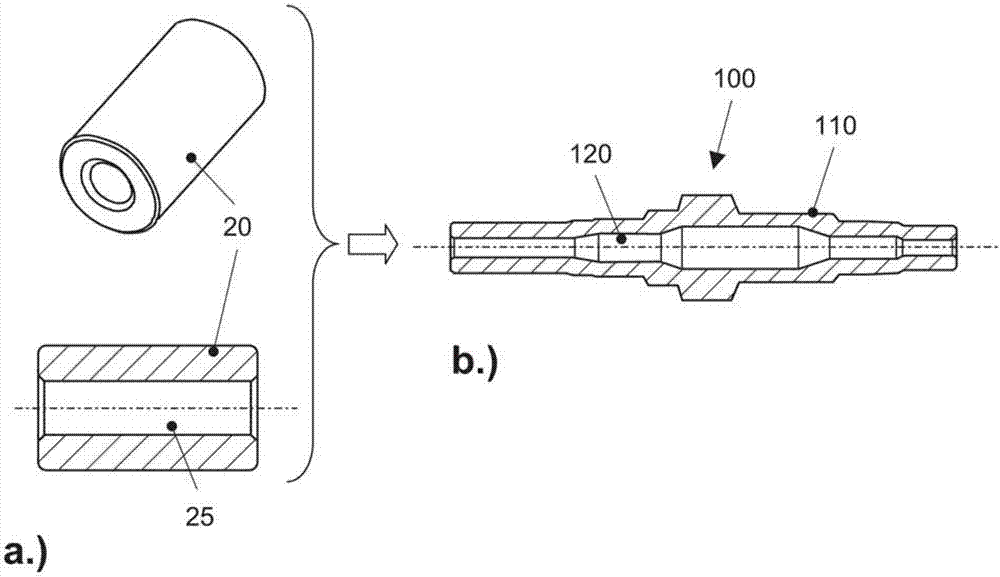
[0041] figure 1 b shows a sectional view of a shaft base body 100 for a hollow drive shaft, here the main shaft of the transmission. The shaft base body 100 has an outer contour 110 and an undercut inner contour 120 , which has a plurality of sections of different diameters. The shaft base 100 is made of the figure 1 The blank 20 shown in a is made. The cylindrical blank 20 is pre-drilled and has coaxial, cylindrical holes 25 .

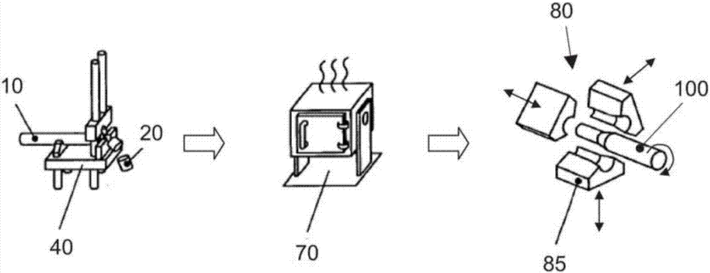
[0042] figure 2 The main steps in the manufacture of the shaft base body 100 are illustrated. In the cutting device 40 or the separating device 40 , the blank 20 is separated from the tubular semi-finished rod 10 . The tubular semi-finished rod 10 is made of steel with a ferritic-pearlitic structure. The blank 20 is heated by means of the heating device 70 to a temperature slightly below the Ac1 temperature (723°C). The heating device 70 is, for example, a furnace. This heating can also advantageously take place by means of an inductive heati...


PUM


Abstract

The invention relates to a method for producing a transmission shaft for a vehicle transmission, comprising the steps of: providing a blank (20) made of steel and having a ferrite-pearlite structure; heating the blank (20) to a temperature below the Ac1 temperature; generating a corrugation base body (100) by incremental radial transformation of the heated blank (20); producing at least one tooth portion (100) on the shaft basic body. In an alternative method, it is provided that a preform is first produced by forging the blank (20).

Description

technical field [0001] The present invention relates to a method for manufacturing a drive shaft of a vehicle transmission. Background technique [0002] In vehicle transmissions, which are preferably transmissions (gearboxes) and in particular automatic transmissions, a drive shaft of this type is used to transmit torque, for which the drive shaft has at least one toothing (working toothing, socket toothing) part) and optionally also at least one bearing surface for a so-called fixed gear. A drive shaft of the type described can also be used to support at least one so-called floating gear. [0003] The manufacture of such a drive shaft is expensive and many method steps or process steps are carried out in sequence, which must be carried out very carefully in order to avoid damage to the transmission. [0004] The closest prior art DE 10 2008 036 226 A1 describes a method for producing a one-piece hollow drive shaft, comprising the steps of: producing a parison by forging,...

Claims


Application Information

Patent Timeline
Patent Type & Authority Applications(China)
IPC IPC(8): B23P15/14
CPCB23P15/14B21J1/02B21J1/06B21J5/008B21K1/063
Inventor S.吕施M.雅布隆斯基
Owner VOLKSWAGEN AG
Why Eureka
Try Eureka