Novel vane wheel and installing method thereof
An installation method and impeller technology, which is applied to the components of the pumping device for elastic fluids, non-variable-capacity pumps, machines/engines, etc., can solve the problem of long time for blade angle adjustment, complicated installation methods, low work efficiency, etc. problems, to achieve the effect of simple installation method, avoiding multiple inspections, and high work efficiency
- Summary
- Abstract
- Description
- Claims
- Application Information
AI Technical Summary
Problems solved by technology
Method used
Image

Examples
Embodiment 1
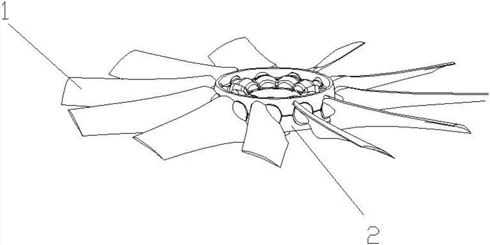
[0051] Refer to attached Figure 1-3 As shown, a new type of impeller provided by the present invention includes several blades 1 and a hub 2, and several blades 1 are uniformly installed on the hub 2; An installation groove, the blade 1 is installed in the hub 2 through the installation groove;
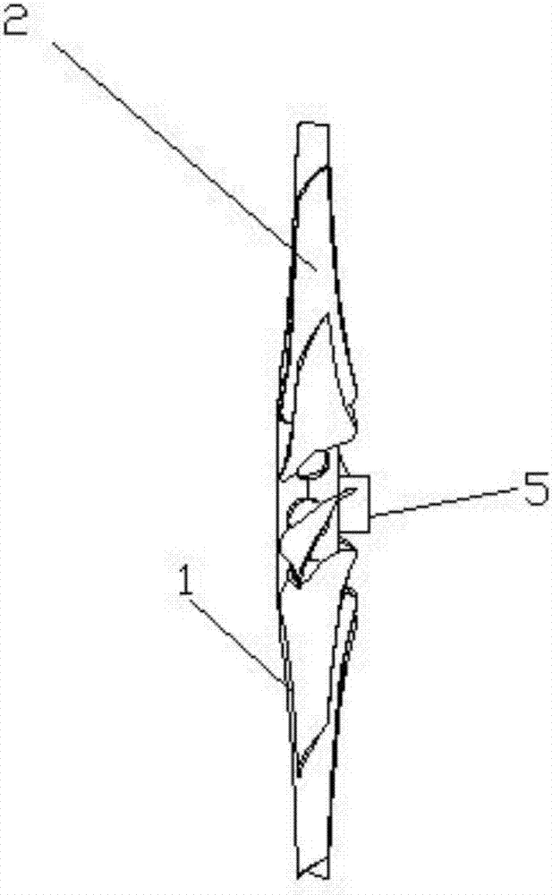
[0052] Refer to attached Figure 4 As shown, wherein, the blade 1 includes a blade surface 101 and a petiole 102, and the petiole 102 is provided with a conical structure 3;
[0053] Further, the petiole 102 also includes a cylindrical connecting piece 4. When there are two truncated conical structures 3, they are respectively the first truncated circular structure 301 and the second truncated circular structure 302. At this time, the first truncated circular structure 301 and the second truncated circular structure 302 are respectively provided at both ends of the cylindrical connector 4 .
[0054] During installation, two truncated circular structures 3 and cylindrical connector...
Embodiment 2
[0060] As a further improvement of the above embodiment, this embodiment also includes a shaft sleeve 4 used in conjunction with the hub 2, the end of the hub 2 is provided with a connection port 6, and the shaft sleeve 5 is snapped into the hub 2 Connection port 6.
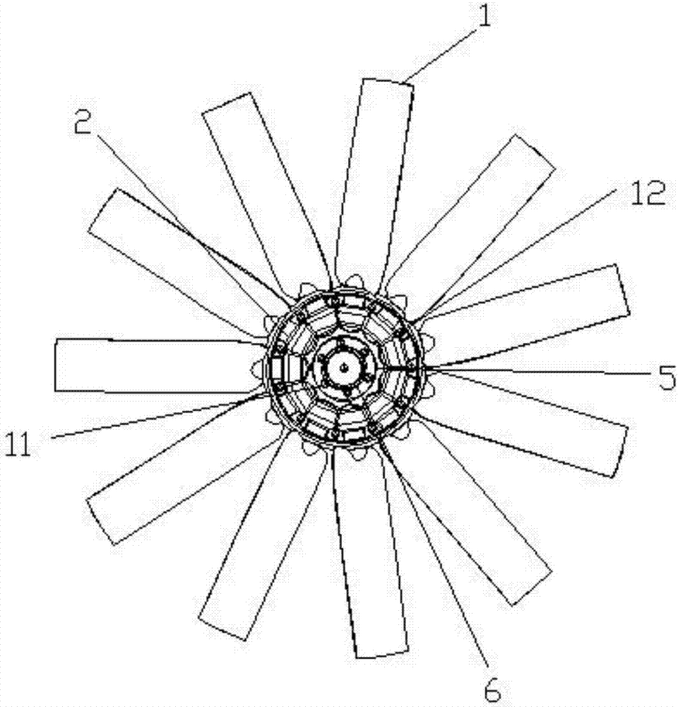
[0061] Refer to attached Figure 5 and 6 As shown, the boss 7 is provided on the shaft sleeve 5 , a through hole 8 is provided on the hub 2 , and a positioning hole 9 is provided on the boss 7 corresponding to the through hole 8 . The through hole 8 and the positioning hole 9 are provided, so that the shaft sleeve 5 and the hub 2 can be locked and installed conveniently through the locking bolt 12 .
[0062] Further, the bushing 5 is an essential part for connecting the impeller and the motor. Firstly, through the bushing 5, the impeller formed by the blade 1 and the hub 2 and the bushing are connected together; secondly, through the through hole 8 and the positioning hole 9 Connect and lock the shaft sleeve 5...
Embodiment 3
[0066] In this embodiment, the hub 2 includes a first hub 201 and a second hub 202 with symmetrical structures. By splitting the hub 2 into a first hub 201 and a second hub 202 with symmetrical structures, the installation of the entire impeller is made simpler. Compared with the prior art, when the hub 2 is integrated, the need for U-shaped clips for installation together is reduced. Or built-in tapered card; reduce the production process, improve production efficiency, increase output, and provide processing accuracy.
[0067] When the hub 2 includes a first hub 201 and a second hub 202 , both the first hub 201 and the second hub 202 are provided with through holes 8 .
[0068] Further, refer to the attached Figure 6 It can be seen that the structures of the first hub 201 and the second hub 202 are symmetrical, and the first hub 201 and the second hub 202 are respectively provided with a plurality of first installation grooves 13 and second installation grooves 14 for inst...
PUM
 Abstract
Description
Claims
Application Information