Carbon dioxide heat pump heat supply system

A heating system, carbon dioxide technology, applied in heating systems, hot water central heating systems, household heating, etc., to achieve the effect of improving heat exchange efficiency, high energy efficiency, and low heating heat attenuation

Active Publication Date: 2017-08-04
JIANGSU SUJING GROUP +1
View PDF6 Cites 9 Cited by
  • Summary
  • Abstract
  • Description
  • Claims
  • Application Information

AI Technical Summary

Problems solved by technology

In actual heating or drying applications, the temperature difference between the inflow and outflow of circulating hot water used to exchange heat with the outside in the heating cycle system is relatively small, for example, at 5-10°C, such high-temperature return water is not suitable for re-use. into the CO2 heat pump system to reheat the

Method used


Image

  • Carbon dioxide heat pump heat supply system

Examples


Embodiment Construction

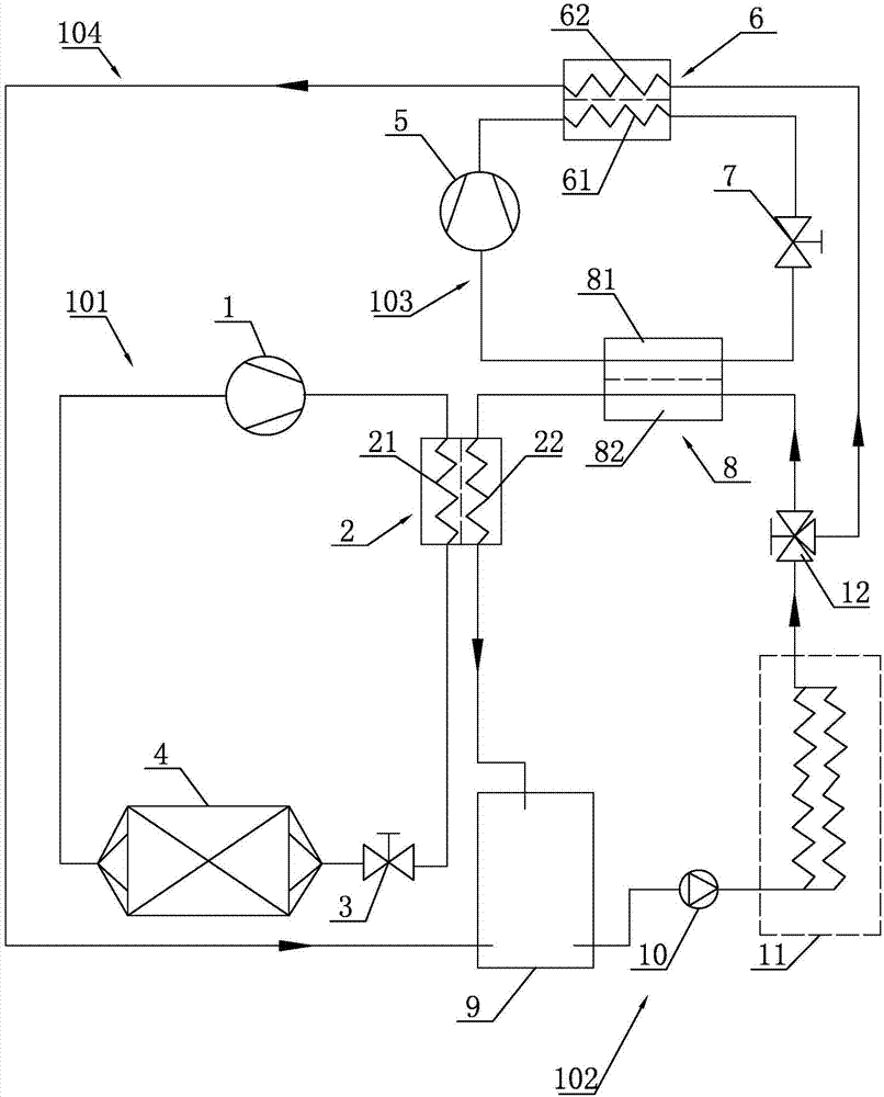
[0027] Such as figure 1 As shown, a carbon dioxide heat pump heating system according to the present invention includes a control unit (not shown). The control unit can control the heating system to supply heat to the heating area. The heating system also includes a first circulation loop 101 , a heating circulation loop 102 , a second circulation loop 103 and a distribution pipeline 104 . A gas cooler ( 2 ) is arranged between the first circulation loop 101 and the heating circulation loop 102 . The gas cooler 2 has a first heat exchange pipeline 21 and a second heat exchange pipeline 22 arranged adjacently. A second evaporator 8 is arranged between the heating circulation loop 101 and the second circulation loop 102 . The second evaporator 8 has a third heat exchange pipeline 81 and a fourth heat exchange pipeline 82 arranged adjacently. A condenser 6 is provided between the second circulation loop 103 and the split pipeline 104 . The condenser 6 has a fifth heat exchan...


PUM


Abstract

The invention relates to a carbon dioxide heat pump heat supply system. The carbon dioxide heat pump heat supply system comprises a first circulating loop, a heat supply circulating loop, a second circulating loop and a shunting pipeline, wherein carbon dioxide is used as a refrigerant in the first circulating loop; circulating water is used as a medium in the heat supply circulating loop; and Freon is used as a refrigerant in the second circulating loop. A gas cooler is arranged between the first circulating loop and the heat supply circulating loop, and a second evaporator is arranged between the heat supply circulating loop and the second circulating loop. The gas cooler is used for carrying out heat exchange between the carbon dioxide and the circulating water. The second evaporator is used for lowering the temperature of the circulating water. By adopting the second circulating loop to lower the temperature of the circulating water entering the gas cooler, the temperature difference between the inlet water and the outlet water of the gas cooler is increased, and the transcritical circulating heat exchange efficiency of the first circulating loop is increased. The heat supply system can stably and efficiently run at low environmental temperature. Heating capacity attenuation is low, the energy efficiency is high, and high-temperature heating or drying can be realized.

Description

technical field [0001] The invention belongs to the field of heating equipment, and in particular relates to a heating system used in a low-temperature environment. Background technique [0002] At present, in a low-temperature environment, such as an extremely cold weather environment of -28°C, a heating system that can adapt to environmental needs is required to provide heat for indoors and other places. Conventional heating systems, such as those using Freon as a refrigerant, simply cannot operate stably in extremely cold weather at -28°C. And with the reduction of ambient temperature, the heating capacity of this heating system attenuates very badly. [0003] However, the existing heat pump system using carbon dioxide as a refrigerant can be used in this ultra-low temperature environment. However, most of the existing carbon dioxide heat pump systems are limited to supplying hot water, and are rarely used in heating and circulating heating. Even if the carbon dioxide ...

Claims


Application Information

Patent Timeline
Patent Type & Authority Applications(China)
IPC IPC(8): F25B9/00F24D3/18F24D19/10F26B23/00
CPCF24D3/18F24D19/1039F25B9/008F26B23/00F25B2309/06
Inventor 汤晓亮熊丹尤军周大农康强宋晓飞
Owner JIANGSU SUJING GROUP
Why Eureka
Try Eureka