Carbon dioxide heat pump system and control method thereof

A technology for carbon dioxide and heat pump systems, applied in heat pumps, refrigerators, refrigeration components, etc., can solve problems such as damage to carbon dioxide heat pump systems, and achieve the effects of extending effective heating time, reducing exhaust temperature, and improving evaporation efficiency.

Pending Publication Date: 2017-09-05
JIANGSU SUJING GROUP +1
View PDF5 Cites 5 Cited by
  • Summary
  • Abstract
  • Description
  • Claims
  • Application Information

AI Technical Summary

Problems solved by technology

In actual heating or drying applications, the temperature difference between the inlet and outlet water of the circulating hot water used to exchange heat with the outside in the heating cycle system is relatively small, for example, at 5-10°C, such high-temperature return water is not suitable for recycling. Entering the carbon dioxide heat pump system to reheat, forcibly using it will cause damage to the carbon dioxide heat pump system

Method used


Image

  • Carbon dioxide heat pump system and control method thereof

Examples


Embodiment Construction

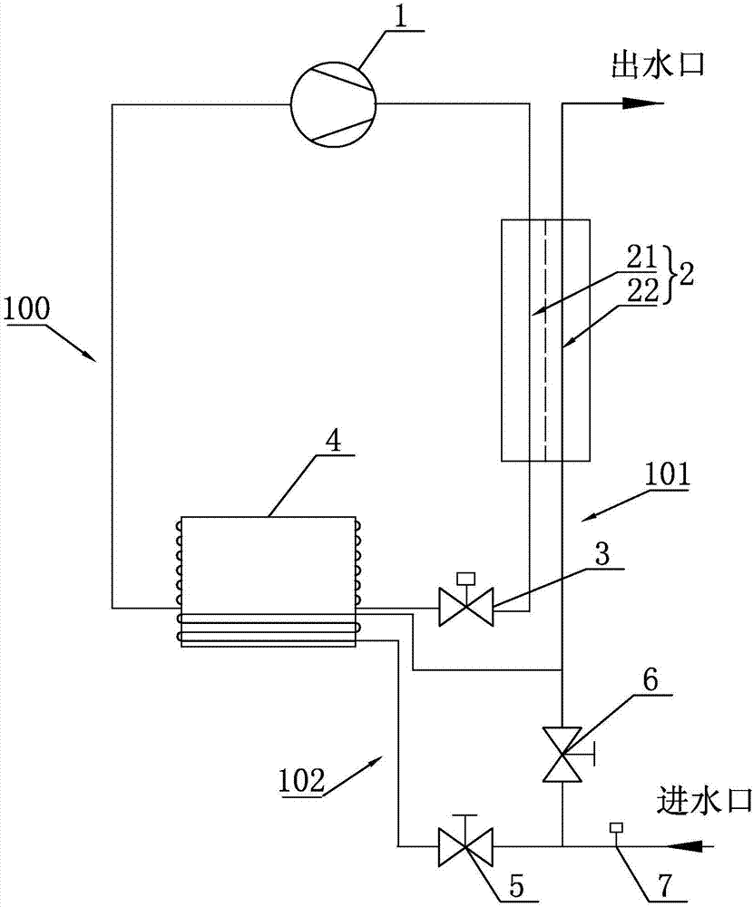
[0030] Such as figure 1 As shown, a carbon dioxide heat pump system according to the present invention includes a control unit (not shown in the figure), a carbon dioxide circulation loop 100 , a hot water supply circuit 101 and a pre-cooling water circuit 102 . The control unit can control the carbon dioxide heat pump system to supply heat or hot water to the outside. The control unit described in this embodiment is an existing common controller, such as PLC, and the control unit is not the technical point of this application, so it will not be described in detail here, and the existing structure that can realize the control function shall prevail.

[0031] The carbon dioxide circulation loop 100 is used for circulation of carbon dioxide. Both the hot water supply circuit 101 and the pre-cooling water circuit 102 are used for water supply and circulation. The carbon dioxide circulation loop 100 is provided with a carbon dioxide compressor 1 , a gas cooler 2 , a throttling m...


PUM


Abstract

The invention relates to a carbon dioxide heat pump system. The carbon dioxide heat pump system comprises a carbon dioxide circulating loop, a heat supply water way and a precooling water way. A carbon dioxide evaporator and a gas cooler are arranged in the carbon dioxide circulating loop; a carbon dioxide channel and a hot water channel are adjacently arranged in the gas cooler; and the carbon dioxide channel is connected with a refrigerant pipeline. A temperature sensor and a first valve are arranged in the heat supply water way; and the first valve is connected with an inlet of the hot water channel. A second valve is arranged in the precooling water way; a pipeline of the precooling water way penetrates through the carbon dioxide evaporator, and is near the refrigerant pipeline; an inlet of the precooling water way is connected with a water inlet of the heat supply water way; and an outlet is connected with an inlet of the hot water channel. Water fed in the heat supply water way is controlled to enter the carbon dioxide evaporator for precooling. The carbon dioxide heat pump system can effectively and precisely compensate the efficiency attenuation when the water inlet temperature is higher, and can effectively increase the water inlet and outlet temperature difference of the gas cooler to prolong the service life.

Description

technical field [0001] The invention belongs to the field of heating equipment, and in particular relates to a carbon dioxide heat pump system. Background technique [0002] At present, the use scenarios of carbon dioxide heat pump systems are limited. Most of the existing carbon dioxide heat pump systems are limited to supplying hot water, and are rarely used in heating and circulating heating. Even if the carbon dioxide heat pump system is used, most of them operate under the condition that the inlet water temperature of the carbon dioxide heat pump does not exceed about 40°C. This is because the carbon dioxide heat pump is more suitable for the heating mode with a large temperature difference between the inlet and outlet water, but not for the heating mode with a small temperature difference between the inlet and outlet water. When the inlet water temperature is too high, the exhaust pressure and temperature of the compressor in the carbon dioxide heat pump system and th...

Claims


Application Information

Patent Timeline
IPC IPC(8): F25B30/02F25B49/02
CPCF25B30/02F25B49/02
Inventor 汤晓亮熊丹尤军周大农康强宋晓飞
Owner JIANGSU SUJING GROUP
Why Eureka
Try Eureka