Magnetic motor

A magnetic motor and magnetic strip technology, applied in the field of magnetic motors, can solve the problems of small distribution area of ​​repulsive force, inability to improve power working ability, and low efficiency of energy conversion.

Inactive Publication Date: 2017-08-04
张民方
View PDF5 Cites 2 Cited by
  • Summary
  • Abstract
  • Description
  • Claims
  • Application Information

AI Technical Summary

Problems solved by technology

[0004] Therefore, the technical problem to be solved by the embodiment of the present invention is that the magnetic motor in the prior art can only generate repulsive force on the rack on the opposite side of the inner wall of the stator and the outer wall of the rotor, so the distribution area of ​​the repulsive force is small, and the power working ability cannot be improved. Therefore, the efficiency of energy conversion is relatively low technical problem

Method used


Image

  • Magnetic motor
  • Magnetic motor
  • Magnetic motor

Examples


Embodiment 1

[0036] This embodiment provides a magnetic motor. The magnetic motor is used as a general power drive source in the technical field of power equipment. It utilizes the working principle that the same type of magnetic poles repel each other and different types of magnetic poles attract each other. In the magnetic field, repulsion or suction is generated to perform power work. Make the magnetic motor rotate normally, thereby driving other objects or vehicles to move. Magnetic motors can use magnets or energized coils to generate magnetic force to form magnetic energy. Compared with gas, coal and gasoline as energy sources for power equipment, it is obvious that magnetic energy is not only more environmentally friendly, but also can make full use of magnetic energy and magnetic properties. The characteristics of unrestricted independent movement can replace other conventional energy sources to meet the needs of social development.

[0037] The magnetic motor in this embodiment, s...

Embodiment 2

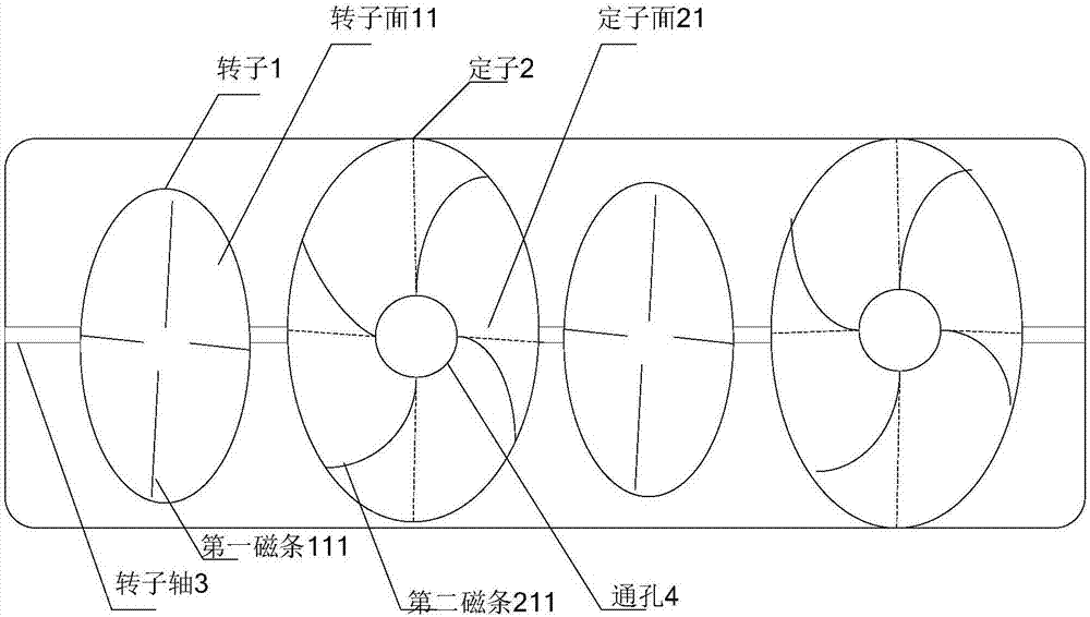
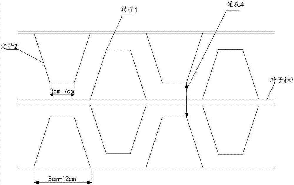
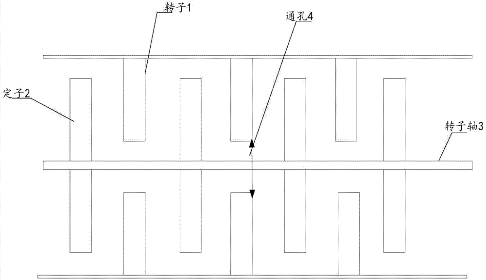
[0046] This embodiment provides a magnetic motor, including a stator 2 and a rotor 1, the rotor 1 is arranged on the rotor shaft 3, the stator 2 is arranged on the stator shell, the rotor shaft 3 is located in the center of the stator shell, and the rotor 1 and the stator 2 are arranged according to the preset Interlaced and juxtaposed at intervals, the stator 2 is formed with a through hole 4 for the passage of the rotor shaft 3, the rotor surface 11 of the adjacent rotor 1 and the stator 2 is opposite to the stator surface 21, and the stator 2 and the rotor 1 are arranged according to a preset interval , and the adjacent rotor surface 11 is parallel to the stator surface 21, such as Figure 5 It is shown that the first magnetic strips 111 extending radially from the rotor shaft 3 to the outer edge of the rotor surface 11 are arranged at intervals on the rotor surface 11, and the first magnetic strips 111 have a first inclined plane obliquely intersecting with the rotor surfac...


PUM

PropertyMeasurementUnit
Thicknessaaaaaaaaaa
Thicknessaaaaaaaaaa

Abstract

The invention discloses a magnetic motor, and the magnetic motor comprises stators and rotors. The rotors re disposed on a rotor shaft, and the stators are disposed on a stator housing. The rotor shaft is located at the center of the stator housing. The magnetic motor is characterized in that the rotors and the stators are arranged in parallel at a preset interval in a staggered manner; the stators are respectively provided with a through hole which is used for the passing of the rotor shaft; the rotor surface and stator surface of the adjacent rotors and stators are opposite; the rotor surface is provided with first magnetic strips at intervals, wherein the magnetic strips extend radially to the outer edge of the rotor surface from the rotor shaft; the stator surface is provided with second magnetic strips which extend in a non-radial direction to the edge of the stator surface from the edge of the through hole; the magnetism of the first magnetic strips and the magnetism of the second magnetic strips are the same, thereby generating a repulsive force to enable the rotors to rotate around the rotator shaft and output power. The stators and the rotors are arranged in parallel in a staggered manner, and the first inclined surfaces of the first magnetic strips are opposite to the second inclined surfaces of the second magnetic strips, thereby generating a large-area repulsive force, enabling the rotors to output strong power, and improving the energy conversion efficiency.

Description

technical field [0001] The invention relates to the technical field of power equipment, in particular to a magnetic motor. Background technique [0002] The magnetic motor is a principle that uses permanent magnets or electromagnets to drive the rotor to move, and is a drive device that converts magnetic energy into kinetic energy. Usually, the permanent magnet of the magnetic motor or the magnetic force of the current-carrying conductor is used to drive the rotor to do work, which is used as the driving source to drive the object to move. [0003] At present, the magnetic motors in the prior art generally use rectangular vertical permanent magnets arranged on the inner wall of the stator and the outer wall of the rotor, and the magnetic poles of adjacent magnets are alternately arranged, and the rotation is carried out by using the principle of mutual repulsion and mutual attraction between the magnetic poles. For work, because of its relatively simple structure, the magne...

Claims


Application Information

Patent Timeline
IPC IPC(8): H02K53/00
CPCH02K53/00
Inventor 张民方
Owner 张民方
Why Eureka
Try Eureka