Tension-leg offshore floating wind turbine foundation capable of floating and being installed by self and installation method thereof

A wind turbine foundation and tension leg technology, which is applied to floating buildings, anchoring arrangements, transportation and packaging, etc., can solve the problems of insufficient economy of floating foundations, high installation costs of large crane ships, etc., and achieve convenient installation. Low cost, low maintenance cost and widely applicable effect

Pending Publication Date: 2017-08-08
CHINA NAT OFFSHORE OIL CORP +2
View PDF9 Cites 19 Cited by
  • Summary
  • Abstract
  • Description
  • Claims
  • Application Information

AI Technical Summary

Problems solved by technology

This invention uses a suction caisson to avoid offshore piling operations. The suction caisson is connected to the bottom of the floating foundation in advance, but a large crane is needed to lift the floating foundation and the suction caisson into the sea during installation. The problem of high installation cost brought by the use of crane ships makes the floating foundation economical still insufficient

Method used


Image

  • Tension-leg offshore floating wind turbine foundation capable of floating and being installed by self and installation method thereof
  • Tension-leg offshore floating wind turbine foundation capable of floating and being installed by self and installation method thereof
  • Tension-leg offshore floating wind turbine foundation capable of floating and being installed by self and installation method thereof

Examples


Embodiment Construction

[0037] Embodiments of the present invention are described in detail below, examples of which are shown in the drawings, wherein the same or similar reference numerals designate the same or similar elements or elements having the same or similar functions throughout. The embodiments described below by referring to the figures are exemplary and are intended to explain the present invention and should not be construed as limiting the present invention.

[0038] In describing the present invention, it should be understood that the terms "center", "longitudinal", "transverse", "length", "width", "thickness", "upper", "lower", "front", " Orientation or position indicated by "back", "left", "right", "vertical", "horizontal", "top", "bottom", "inner", "outer", "clockwise", "counterclockwise", etc. The relationship is based on the orientation or positional relationship shown in the drawings, and is only for the convenience of describing the present invention and simplifying the descrip...


PUM


Abstract

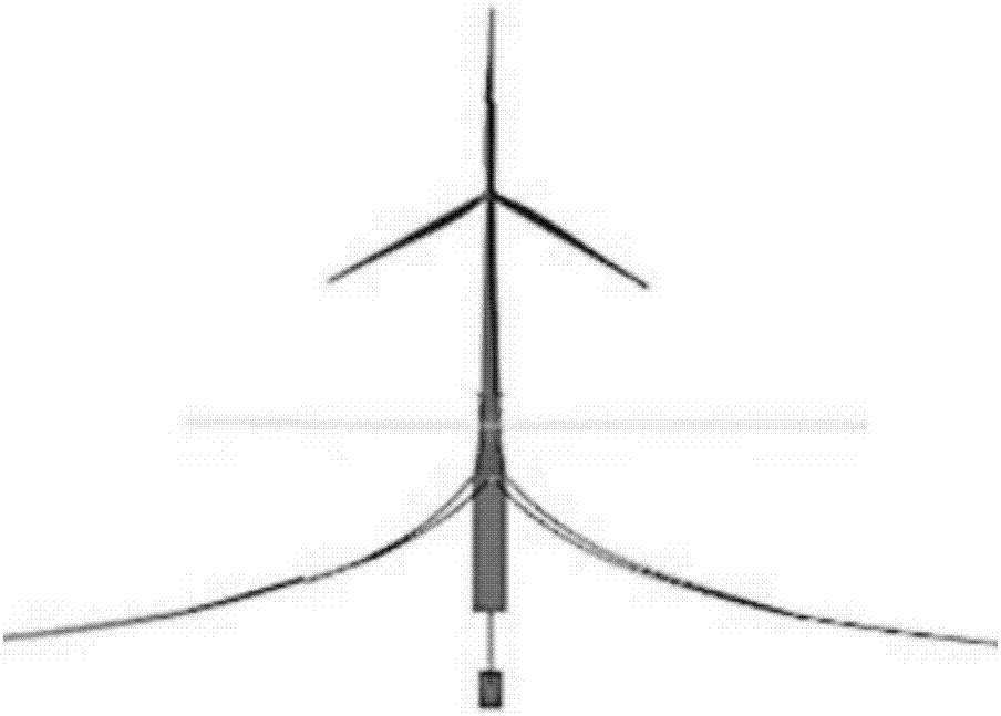
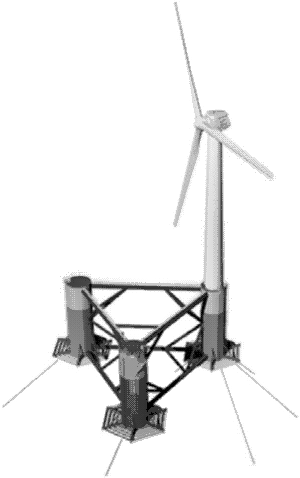
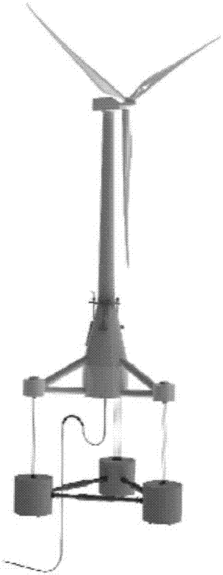
The invention discloses a tension-leg offshore floating wind turbine foundation capable of floating and being installed by self and an installation method thereof. The tension-leg offshore floating wind turbine foundation comprises three rectangular floating boxes on a same horizontal plane and of which any two are at an included angle of 120 degrees, a center floating box connecting the three rectangular floating boxes, a center pillar connected with the upper end of the center floating box and used for supporting a wind turbine tower, three peripheral pillars which are in a one-to-one connection with the three rectangular floating boxes and separated from each other, three cantilever beams respectively and correspondingly arranged at the top of the three peripheral pillars and extending outwardly, a heave plate connected to the bottom of the three rectangular floating boxes and the center pillar, transverse braces and diagonal braces for connecting the center pillar and the peripheral pillars, a subsea base part and tension legs for connecting the cantilever beams and the subsea base part. The tension-leg offshore floating wind turbine foundation capable of floating and being installed by self according to an embodiment of the invention has the advantages of low cost for later maintenance, convenient installation and low installation cost.

Description

technical field [0001] The invention relates to the technical field of wind power generation, in particular to a tension-leg offshore floating wind turbine foundation capable of self-floating installation and an installation method thereof. Background technique [0002] Fan is a device that converts wind energy into mechanical energy and then into electrical energy. It is mainly installed in windy areas on land and offshore areas. Because it is not affected by building shelter or terrain fluctuations, offshore wind resources have higher availability and stability than land wind resources. Therefore, in recent years, offshore wind power installations have become a hot topic in the development of various wind power fields. Initially, offshore wind power installations were installed in offshore shallow water areas, generally with a water depth of less than 20 meters and hundreds of meters to 10 kilometers offshore. The foundation of the wind power installations generally used ...

Claims


Application Information

Patent Timeline
Patent Type & Authority Applications(China)
IPC IPC(8): B63B35/44B63B21/50B63B9/06
CPCB63B21/502B63B35/44B63B2035/446B63B75/00B63B73/00
Inventor 罗勇许鑫朱为全王铭飞李欣王艳
Owner CHINA NAT OFFSHORE OIL CORP
Why Eureka
Try Eureka