Antivibration kit-of-parts and parts therefor, airfoil structure and aircraft provided therewith

a technology of airfoil structure and parts, applied in the field of parts, can solve the problems that the control surface, such as the rudder, the elevator, the ailerons, etc., may start to flutter or vibrate due to air flow, and achieve the effect of avoiding or reducing vibrations

Pending Publication Date: 2022-03-24
AIRBUS OPERATIONS GMBH
View PDF5 Cites 0 Cited by
  • Summary
  • Abstract
  • Description
  • Claims
  • Application Information

AI Technical Summary

Benefits of technology

[0004]It is an object of the invention to provide measures which improve resilience, in particular, of control surfaces, against vibration or flutter in aircraft.
[0011]Preferably, when both the spring device and the cam device are in the operating condition, the deflection of the spring device decreases when the cam device is moved from a cam device neutral position in a first direction but not another direction.
[0060]Preferably, the deflection of the spring device decreases when the cam device is moved from a cam device neutral position in a first direction but not another direction.
[0095]The basic idea is to install a cam device in the vertical tail plane (VTP), for example. The cam device aims to apply a permanent torque on the rudder, when its deflection is zero degrees and decreases the torque with increasing rudder angle, when the rudder is moved to either side. By applying this torque, vibrations on movable structures, in particular in a cruise condition, may be reduced. Thus, wear is reduced, so that an increase in limit cycle oscillations (LCO) severity is avoided. While a solution could be based on light metal material (titanium, aluminum, etc.), another solution may use fiber composite materials, such as carbon fiber reinforced plastics (CFRP) or glass fiber reinforced plastics (GFRP). Using composites, the same function can be achieved while at the same time weight of the device is reduced. In addition to being lighter and significantly cheaper and easier to install, the cam device may also be installed to any hinge fitting present in an aircraft. In other words, the cam device and corresponding spring device are compatible with any wing, horizontal tail plane (HTP), vertical tail plane (VTP) and corresponding movable surfaces potentially affected by vibrations, such as high lift devices and control surfaces. Furthermore, the idea is applicable to any type aircraft but preferably airplanes.
[0100]As a result, an asymmetric torque characteristic is achieved, which allows the application of substantial torque to the rudder in the cruise condition, so as to avoid or reduce vibrations, whereas movement of the rudder is barely impaired.

Problems solved by technology

Control surfaces, such as rudders, elevators, ailerons, elevons and the like, may start to flutter or vibrate due to air flow, in particular, in cruise conditions.

Method used


Image

  • Antivibration kit-of-parts and parts therefor, airfoil structure and aircraft provided therewith
  • Antivibration kit-of-parts and parts therefor, airfoil structure and aircraft provided therewith
  • Antivibration kit-of-parts and parts therefor, airfoil structure and aircraft provided therewith

Examples


Embodiment Construction

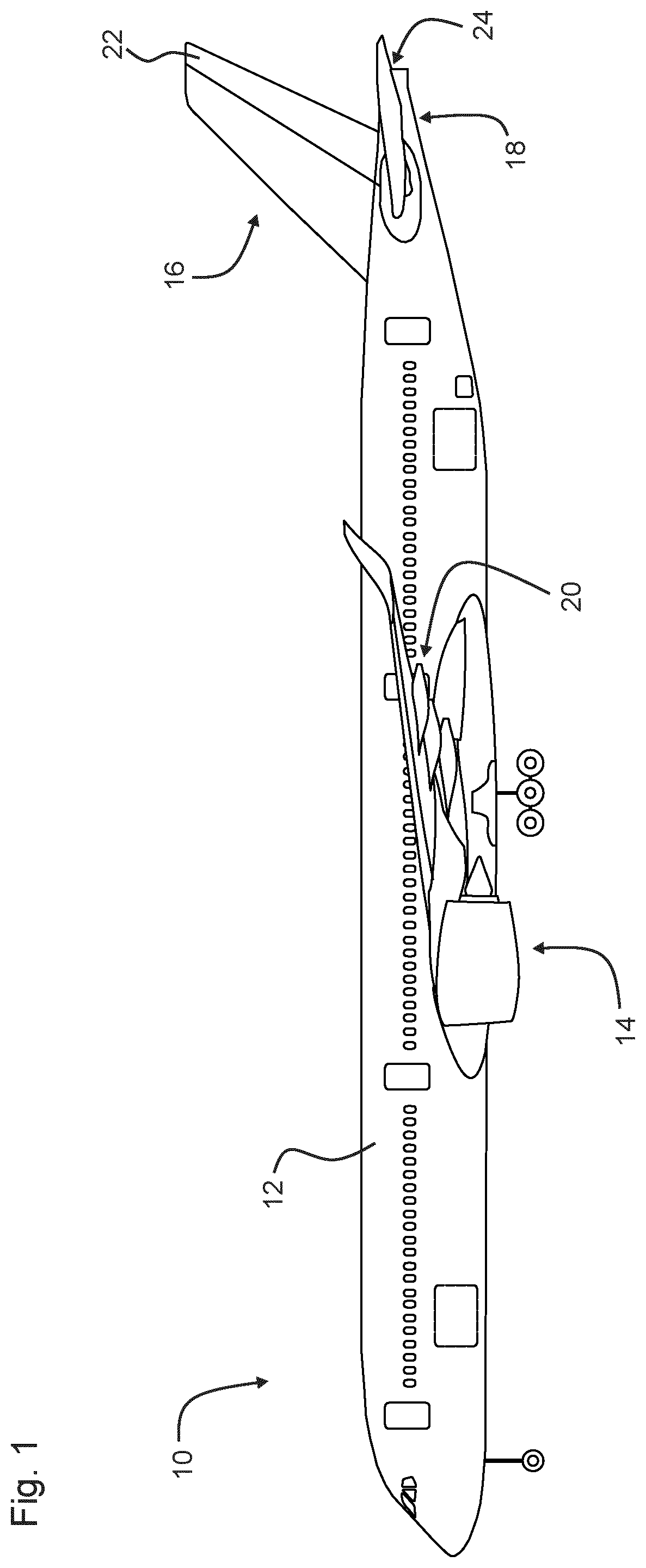
[0114]FIG. 1 depicts an aircraft 10. In a typical manner, the aircraft 10 has a fuselage 12. Furthermore, the aircraft 10 comprises wings 14, a vertical tail plane 16, and a horizontal tail plane 18. The wing 14 comprises ailerons 20. The vertical tail plane 16 has a rudder 22 attached to it. Furthermore, the horizontal tail plane 18 comprises an elevator 24.

[0115]For the sake of brevity, the invention is described in more detail with reference to the vertical tail plane 16 and the rudder 22. However, the skilled person will recognize that the ideas presented herein are also applicable to the wing 14 and the ailerons 20 as well as the horizontal tail plane 18 and the elevator 24. Furthermore, these ideas are applicable to combinations of control surfaces such as elevons and spoilerons.

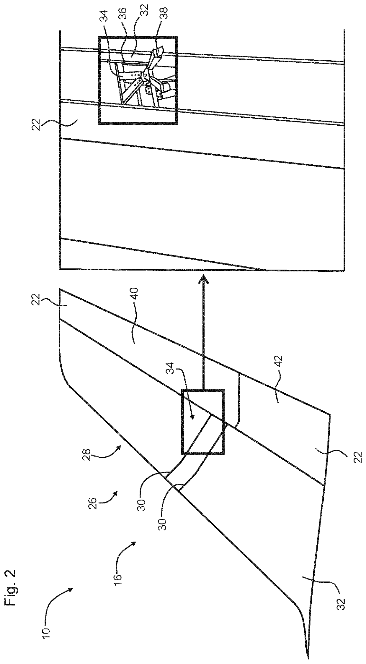
[0116]FIG. 2 depicts in more detail the vertical tail plane 16 as an example for an airfoil structure arrangement 26. The airfoil structure arrangement 26 comprises a airfoil mounting structure 28. The...


PUM

PropertyMeasurementUnit
angleaaaaaaaaaa
angleaaaaaaaaaa
spring forceaaaaaaaaaa

Abstract

To reduce vibration of movable airfoil structures, such as rudders, elevators, and ailerons, a spring device, a leaf spring for example, is mounted to an airfoil mounting structure, such as a vertical tail plane, horizontal tail plane or the wings, such that the spring device exerts a force on a cam device, which transforms the spring force into an airfoil torque. The airfoil torque is applied to the airfoil structure and thus reduces a risk of vibration. The cam device is configured to redirect the spring force such that when the airfoil structure is moved in a first direction, torque decreases and when moved in the opposite second direction the torque is zero.

Description

CROSS-REFERENCES TO RELATED APPLICATIONS[0001]This application claims the benefit of the International Application No. PCT / EP2020 / 064550, filed on May 26, 2020, and of the German patent application No. 102019114313.6 filed on May 28, 2019, the entire disclosures of which are incorporated herein by way of reference.FIELD OF THE INVENTION[0002]The invention relates to an antivibration kit-of-parts configured for reducing vibration of an airfoil structure. The invention further relates to an airfoil structure and an aircraft using the kit-of-parts as well as parts for the kit of parts.BACKGROUND OF THE INVENTION[0003]Control surfaces, such as rudders, elevators, ailerons, elevons and the like, may start to flutter or vibrate due to air flow, in particular, in cruise conditions. While this may be counteracted actively via the hydraulic system, there is a desire for a simpler stand-alone approach.SUMMARY OF THE INVENTION[0004]It is an object of the invention to provide measures which imp...

Claims


Application Information

Patent Timeline
Patent Type & Authority Applications(United States)
IPC IPC(8): B64C9/02B64C13/32F16F1/368
CPCB64C9/02F16F2238/022F16F1/3686B64C13/32F16F3/023F16F1/26F16F15/073F16F15/02B64C13/38B64C9/00B64C9/30B64C5/02B64C5/06B64C2009/005
Inventor BERTOLINI, IVANOLÜTTMANN, HENRIKWESTBROEK, WIM
Owner AIRBUS OPERATIONS GMBH
Why Eureka
Try Eureka