Printing and dyeing equipment with cleaning function

A printing and dyeing equipment and functional technology, which is applied in the field of printing and dyeing equipment with cleaning function, can solve the problems of poor dye absorption, uneven spray dyeing, inconvenient cleaning of dyeing equipment, etc., and achieve the effect of ingenious structure

Inactive Publication Date: 2017-08-08
CHANGXING JIAPU YIHANG TEXTILE FACTORY
View PDF1 Cites 2 Cited by
  • Summary
  • Abstract
  • Description
  • Claims
  • Application Information

AI Technical Summary

Problems solved by technology

[0006] The purpose of the present invention is to overcome the inadequacies of the prior art and overcome the inconvenient cleaning of the dyeing equipment, resulting in more dirt affecting the dyeing effect of the cloth, more wrinkles during the dyeing process of the cloth transmission, uneven spraying and poor absorption of the dye by the cloth. good question

Method used


Image

  • Printing and dyeing equipment with cleaning function
  • Printing and dyeing equipment with cleaning function
  • Printing and dyeing equipment with cleaning function

Examples


Embodiment 1

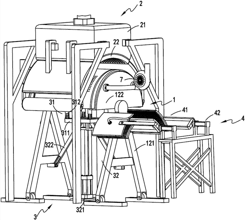
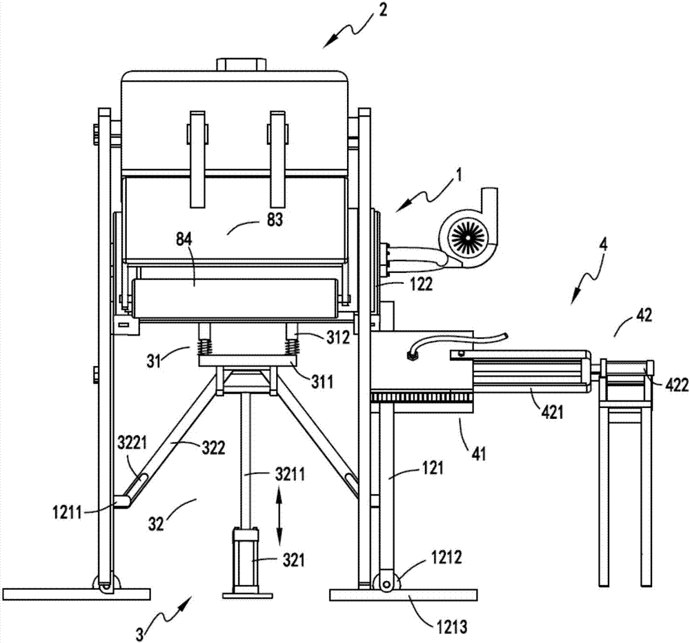
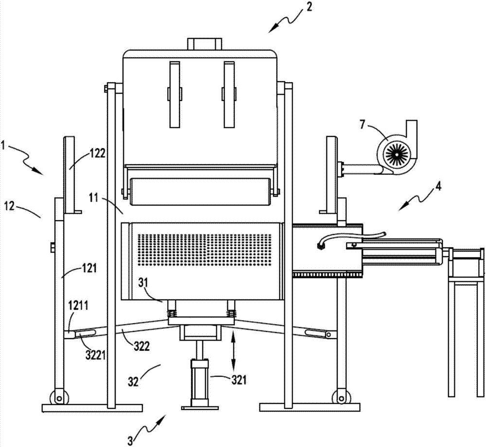
[0045] figure 1 It is a structural schematic diagram of printing and dyeing equipment with cleaning function, figure 2 It is a schematic diagram of the front view of the printing and dyeing equipment with cleaning function in working state, image 3 It is a schematic diagram of the front view of the printing and dyeing equipment with cleaning function in the cleaning state, Figure 4 It is a structural schematic diagram of the bearing part and the lifting part, Figure 5 It is a schematic diagram of the disassembled structure of the bearing part, Figure 6 Schematic diagram of the structure of the buffer bearing assembly, Figure 7It is a schematic diagram of the front view of the spraying part and the bearing part, Figure 8 Schematic diagram of the structure of the cleaning part, Figure 9 It is a schematic diagram of the structure of the scrubbing assembly. Such as figure 1 , figure 2 , image 3 , Figure 4 , Figure 5 , Figure 6 , Figure 7 , Figure 8 and...

Embodiment 2

[0063] Such as figure 1 , figure 2 , image 3 , Figure 4 , Figure 5 , Figure 6 , Figure 7 , Figure 8 and Figure 9 As shown, the components that are the same as or corresponding to those in the first embodiment are marked with the corresponding reference numerals in the first embodiment. For the sake of simplicity, only the differences from the first embodiment will be described below. The difference between the second embodiment and the first embodiment is that the outer port of the wrinkle removal hole 1122 on the left side of the negative pressure chamber a1121 is inclined towards the center position with the center position as the dividing line on the arc-shaped surface, and the outer port of the right side is inclined. The outer port of the corrugation hole 1122 is also inclined towards the center position.

[0064] The negative pressure chamber a1121 and the wrinkle removal hole 1122 are set in the wrinkle removal unit 112 to smooth the cloth before sprayin...


PUM


Abstract

The invention relates to printing and dyeing equipment with a cleaning function. The printing and dyeing equipment comprises a bearing part, a printing and dyeing part arranged above the bearing part, a lifting part, and a cleaning part, wherein the bearing part comprises a support component and sealing and fixing components; the support component comprises a support unit, a wrinkle removing unit and an absorbing unit; the lifting part comprises a buffer bearing component and a drive component; when the buffer bearing component is driven by a drive component to do lifting movement, the sealing and fixing components installed at the two end parts of the support component in a symmetrical matching manner synchronously move oppositely and reversely in the length direction of the support component, and the support component is driven by the buffer bearing component to move up and down; the cleaning part comprises a rinsing component and a telescopic component, and the rinsing component is driven by the telescopic component to clean the support component. The printing and dyeing equipment solves the problems that the dyeing equipment is not convenient to clean, the dyeing effect of a fabric is affected by too much dirt, and a dye is not evenly sprayed and the permeation of the dye is not good because of a large amount of wrinkles in the dyeing process of the fabric.

Description

technical field [0001] The invention relates to the technical field of textiles, in particular to a printing and dyeing device with a cleaning function. Background technique [0002] There are generally two types of fabric dyeing techniques, painting and dip-dyeing. Exhaust dyeing method pollutes a lot and wastes materials. For painting and dyeing, the existing painting and dyeing equipment has the problems of uneven dyeing and incomplete absorption of dye by the cloth. [0003] A Chinese utility model patent with the authorized announcement number CN203782393U discloses a high-efficiency small bath ratio open-width spray dyeing machine. Water-based; however, the device has the following problems: [0004] 1. The long-term use of the equipment will produce dirt. After a lot of dirt accumulation, it will lead to uneven transmission in the subsequent fabric dyeing process and poor dyeing effect. The equipment is not easy to clean. [0005] 2. When the spraying mechanism spr...

Claims


Application Information

Patent Timeline
Patent Type & Authority Applications(China)
IPC IPC(8): D06B1/02D06B5/08D06B23/04D06B23/30D06B23/00
CPCD06B1/02D06B5/08D06B23/00D06B23/04D06B23/30
Inventor 嵅奇
Owner CHANGXING JIAPU YIHANG TEXTILE FACTORY
Why Eureka
Try Eureka