Piezoresistive pressure sensor

A pressure sensor, piezoresistive technology, applied in the direction of measuring fluid pressure, fluid pressure measurement by changing the ohmic resistance, and measurement of the property force of the piezoelectric resistance material, which can solve problems such as complex design

Active Publication Date: 2017-08-08
ASIA PACIFIC MICROSYST
View PDF6 Cites 3 Cited by
  • Summary
  • Abstract
  • Description
  • Claims
  • Application Information

AI Technical Summary

Problems solved by technology

Because this structure involves stress film layer stacking, it is more complicated to design

Method used


Image

  • Piezoresistive pressure sensor
  • Piezoresistive pressure sensor
  • Piezoresistive pressure sensor

Examples


Embodiment Construction

[0025] Before the present invention is described in detail, it should be noted that in the following description, similar elements are denoted by the same numerals.

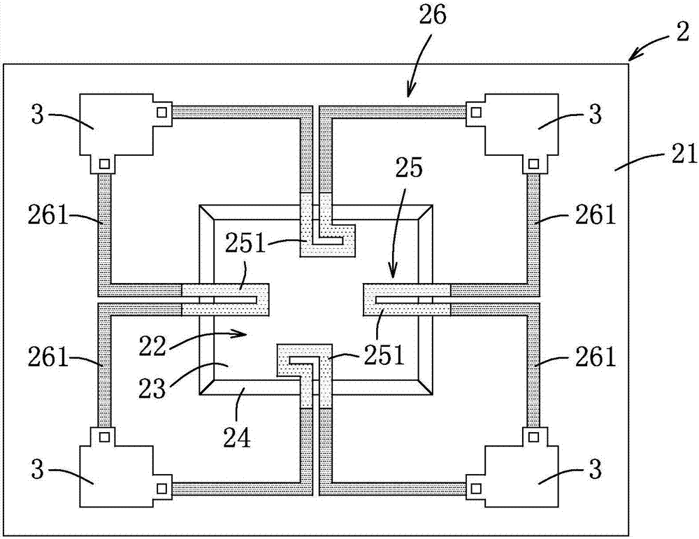
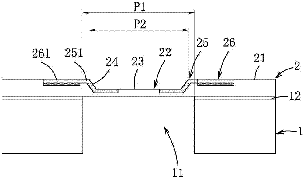
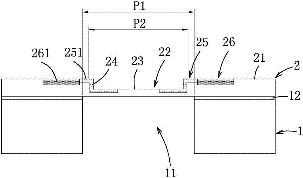
[0026] refer to figure 1 and figure 2 , a first embodiment of the miniature piezoresistive pressure sensor of the present invention includes a substrate 1 and an element structure layer 2 . The substrate 1 forms a vibration space 11 and an insulating layer 12 . The element structure layer 2 is located on the substrate 1 and has an upper surface 21, and a groove 22 corresponding to the position of the vibration space 11 is formed on the upper surface 21, thereby forming a gap between the groove 22 and the Vibrable membrane 23 between vibration spaces 11 . That is to say, the vibration space 11 provides a space where the membrane 23 can vibrate. The groove 22 is defined by the film 23 and a side wall 24 connecting the film 23 and the upper surface 21 . The element structure layer 2 also forms a piezoresistive...


PUM

PropertyMeasurementUnit
thicknessaaaaaaaaaa
thicknessaaaaaaaaaa
thicknessaaaaaaaaaa

Abstract

A piezoresistive pressure sensor includes a substrate and a silicon device layer. The substrate has a cavity. The silicon device layer includes a diaphragm and a support element. A top surface of the diaphragm is connected to a top surface of the support element by one or more side surfaces. A recess of the silicon device layer is defined by the top surface of the diaphragm and the one or more side surfaces. A plurality of piezoresistive regions are on the top surface of the diaphragm, on the one or more side surfaces and on the top surface of the support element. A plurality of conductive regions are on the top surface of the support element. The plurality of conductive regions do not extend to the top surface of the diaphragm. The plurality of piezoresistive regions have a first ion dosage concentration. The plurality of conductive regions have a second ion dosage concentration. The second ion dosage concentration is greater than the first ion dosage concentration.

Description

technical field [0001] The invention relates to a miniature piezoresistive pressure sensor, in particular to a miniature piezoresistive pressure sensor manufactured by ion implantation technology. Background technique [0002] Ion implantation technology is one of the mature manufacturing processes of piezoresistive pressure sensors, and is used to form piezoresistive elements and wires. However, since the junction depth produced by the ion implantation technique can reach several μm, leakage is likely to occur when the concentration of implanted ions is high and the device layer (or film) is thin. However, in many applications, such as miniature pressure sensors set in cardiac catheters, the volume is usually small, so the area of ​​the film used to sense the pressure is limited, so the design must adjust the film thickness to 1-3 μm to meet the required Output sensitivity, if the structure of the general piezoresistive pressure sensor is directly reduced in size and minia...

Claims


Application Information

Patent Timeline
Patent Type & Authority Applications(China)
IPC IPC(8): G01L1/18
CPCG01L1/18G01L9/0055G01L9/0044G01L9/0047G01L9/06
Inventor 殷宏林江政祎黄煜哲
Owner ASIA PACIFIC MICROSYST
Why Eureka
Try Eureka