Experimental device for simulating pseudo-vibration fault of rotating machinery

A technology for rotating machinery and experimental devices, used in measurement devices, vibration testing, and testing of machine/structural components, etc., can solve problems affecting equipment troubleshooting efficiency, accurate diagnosis, and excessive equipment maintenance, and achieve accurate identification and rapidity. processing effect

Inactive Publication Date: 2017-08-08
XI AN JIAOTONG UNIV
View PDF5 Cites 12 Cited by
  • Summary
  • Abstract
  • Description
  • Claims
  • Application Information

AI Technical Summary

Problems solved by technology

As for a series of false vibration problems induced by axial vibration, because the fault signal formation mechanism is very complex, and the fault characteristics are similar to other faults, it is often difficult to accurately diagnose them in the actual process
Especially in the actual processing of this type of problem, due to the complexity of its mechanism, it is difficult to clearly explain the fault principle to front-line equipment managers and maintenance personnel who lack professional knowledge background, which affects the failure of equipment to a certain extent. Maintenance efficiency, in severe cases, it may even cause over-maintenance of equipment
However, the existing experimental equipment for vibration faults of rotating machinery is still unable to simulate the false vibration faults of rotors induced by axial vibration, which brings a lot of trouble to the precise diagnosis of such false vibration faults.

Method used


Image

  • Experimental device for simulating pseudo-vibration fault of rotating machinery
  • Experimental device for simulating pseudo-vibration fault of rotating machinery
  • Experimental device for simulating pseudo-vibration fault of rotating machinery

Examples


Embodiment Construction

[0018] The present invention will be further elaborated below in conjunction with the accompanying drawings and embodiments.

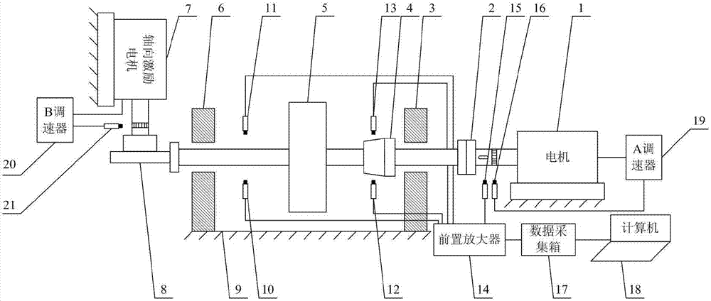
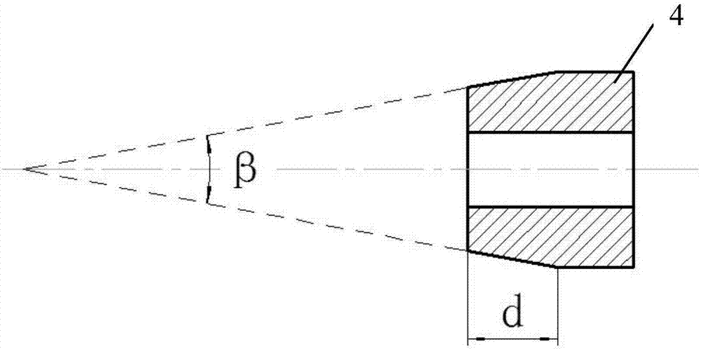
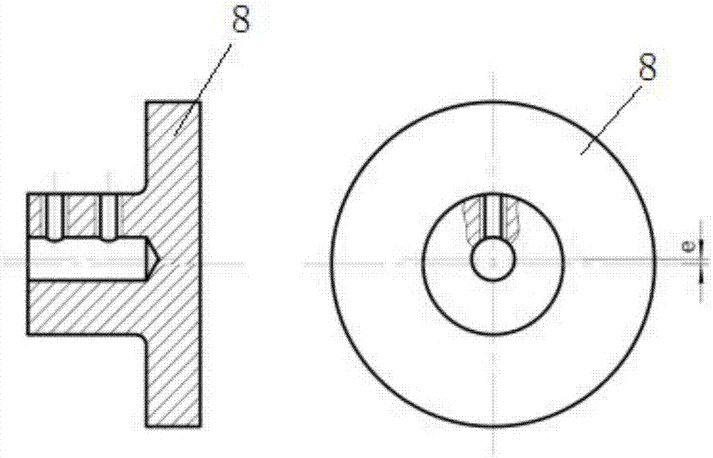
[0019] refer to figure 1 , an experimental device for simulating pseudo-vibration faults of rotating machinery, including a rotor 5, the rotor 5 is supported by a coupling end bearing 3 and a free end bearing 6, the input end of the rotor 5 passes through the flexible coupling 2 and the output shaft of the motor 1 Coaxial connection, a shaft sleeve 4 with surface defects is installed on the rotor 5 close to the bearing 3 at the coupling end, the free side end surface of the rotor 5 keeps in contact with the outer circle of the eccentric wheel 8, and the eccentric wheel 8 is installed on the axial excitation motor 7, the output shaft of the axial excitation motor 7 is perpendicular to the axis of the rotor 5, and the coupling end bearing 3, the free end bearing 6, the motor 1 and the axial excitation motor 7 are all fixed on the base 9 superior;

[00...


PUM


Abstract

The invention provides an experimental device for simulating the pseudo-vibration fault of the rotating machinery. The experimental device comprises a rotor. The rotor is supported by two bearings. The rotor and a motor are coaxially connected. The position of the rotor, closer to the bearings, is provided with a shaft sleeve with a surface defect. The rotor is in contact with the outer circle of an eccentric wheel. The eccentric wheel is mounted on an axial excitation motor. The axial excitation motor is connected with a speed regulator B. The motor is connected with a speed regulator A. Two electrical vortex sensors are aligned with the intact detection surface of the rotor. Two electrical vortex sensors are aligned with the surface defect of the shaft sleeve. The electrical vortex sensors are connected with a computer through a preamplifier and a data acquisition box. The computer is provided with a data acquisition and analysis software. According to the technical scheme of the invention, the device can simulate the pseudo-vibration fault phenomenon caused by the axial vibration, and the fault elimination process thereof. Therefore, the pseudo-vibration fault mechanism caused by the axial vibration can be visually displayed. Meanwhile, the device provides the reference concept and the direct experience for the elimination of the above type of pseudo-vibration faults.

Description

technical field [0001] The invention belongs to the technical field of fault diagnosis of rotating machines, and in particular relates to an experimental device for simulating pseudo-vibration faults of rotating machines. Background technique [0002] Since the vibration signals of rotating mechanical equipment contain a large amount of equipment dynamic information, equipment health monitoring and diagnostic analysis methods based on vibration signals are favored by many researchers at home and abroad, providing extremely important diagnostic information for equipment protection and predictive maintenance. In order to obtain vibration information of equipment, non-contact vibration displacement sensors such as eddy current sensors and laser displacement sensors are widely used in the vibration collection process of rotating machinery. However, the actual measurement results of these sensors are easily affected by the quality of the rotor vibration detection surface and the ...

Claims


Application Information

Patent Timeline
Patent Type & Authority Applications(China)
IPC IPC(8): G01M7/06
CPCG01M7/00
Inventor 林京瞿雷廖与禾赵明陈鹏
Owner XI AN JIAOTONG UNIV
Why Eureka
Try Eureka