
Support

A front pillar and rear pillar technology, which is applied to the support structure of photovoltaic modules, photovoltaic power generation, photovoltaic modules, etc., can solve the problems of poor stability, poor safety, and small external force of the support, and achieve safe and reliable use and low manufacturing cost. , the effect of good support

Inactive Publication Date: 2017-08-08
DONGTAI YINXIN STEEL STRUCTURE ENG CO LTD
View PDF6 Cites 2 Cited by
  • Summary
  • Abstract
  • Description
  • Claims
  • Application Information

AI Technical Summary

Problems solved by technology

[0006] The purpose of the present invention is to provide a bracket to improve the poor stability of the bracket structure in the prior art, the external force it bears is small, and the problem of poor safety in use

Method used


Image

  • Support
  • Support
  • Support

Examples


Embodiment 1

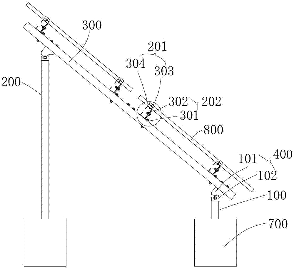
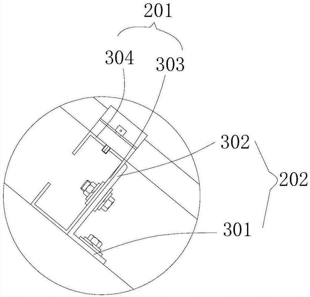
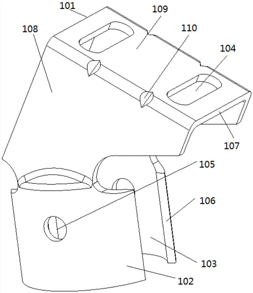
[0041] see Figure 1-3 , the embodiment of the present invention provides a bracket for installing a photovoltaic module 800, including at least one support unit, the support unit includes a front pillar 100, a rear pillar 200, a slanting beam 300, and a plurality of first transfer connectors 400 , the supporting unit is used as the basic unit supporting the photovoltaic module 800, the number of supporting units is set as required, and determined according to the area of ​​the photovoltaic module 800, in order to improve the stability of the photovoltaic module 800 after installation, there are multiple supporting units, multiple The supporting units are arranged at intervals along the length direction of the photovoltaic module 800. Preferably, there are two supporting units. The two supporting units are close to the two ends of the length direction of the photovoltaic module 800. , the photovoltaic module 800 is evenly stressed, and is not easy to fall over.

[0042] Durin...

Embodiment 2

[0054] see Figure 4 , this embodiment also provides a bracket, the transfer connector provided in this embodiment is a further improvement on the basis of the technical solution in the first embodiment, and the disclosed technical solution in the first embodiment is also applicable to this embodiment, In order to avoid repetitive and cumbersome descriptions, the technical solutions already described in Embodiment 1 will not be described again.

[0055] The bracket also includes an oblique strut 500 and a second transfer connector 600, the oblique strut 500 is located between the front strut 100 and the rear strut 200, one end of the oblique strut 500 is hinged to the rear strut 200, the other end of the slanting strut 500 is hinged to the slanting beam 300 through the second adapter. The slanting beam 300 is supported between the front pillar 100 and the rear pillar 200, and can withstand a certain gravity, which further strengthens the firmness of the overall structure of t...


PUM


Abstract

The invention provides a support, and belongs to the field of engineering building auxiliary equipment. The support is used for installing a photovoltaic module and comprises at least one support unit, wherein the support unit comprises a front strut, a rear strut, an oblique beam and a plurality of first connection pieces, each first connection piece comprises a connection part and a cylindrical installation part, an installation hole is formed in the installation part, the connection part is fixed on the installation part and is provided with a positioning plane, the positioning plane is arranged at intervals relative to the installation part along an axial line direction of the installation hole, the axial line of the installation hole and the positioning plane incline, a connection hole is formed in the positioning plane, the front strut and the oblique beam are connected through the first connection piece, and the rear strut and the oblique beam are connected through the first connection piece. The support is firm and reliable in structure, when used for installing the photovoltaic module, the support is good in force bearing and high in seismic resistant and wind resistant capability, and is safe and reliable to use; and after the photovoltaic module is installed, the angle of a cell panel is convenient to determine, the support is not needed to be adjusted, and time and labor are saved during installation.

Description

technical field [0001] The invention relates to the field of engineering construction auxiliary equipment, in particular to a bracket. Background technique [0002] At present, when installing a photovoltaic module, it is necessary to install a bracket at a set position, and the bracket is mostly made of tubular or columnar profiles. In the prior art, the tubular or columnar profiles are fixedly connected by triangular connectors. The triangular piece includes a bottom plate and two connecting plates oppositely arranged, and the two connecting plates are installed on the same plate surface of the bottom plate in parallel and at intervals, and two waist-shaped holes are arranged on the bottom plate, and the two connecting plates There are mounting holes on the top respectively, and the two mounting holes are set coaxially. When installing, place the end of a profile on the two connecting plates, and use bolts to pass through the two mounting holes and the profile to hinge the...

Claims


Application Information

Patent Timeline
IPC IPC(8): H02S20/00H02S20/30
CPCY02B10/10Y02E10/50
Inventor 赵长玉赵长煦方晓琴
Owner DONGTAI YINXIN STEEL STRUCTURE ENG CO LTD
Learn More