Compression data structure method for compressing print data using same and method for printing

A technology for compressing data and printing data, which is applied in printing, copying/marking methods, electrical components, etc., and can solve the problem of large printing data capacity, etc.

Active Publication Date: 2017-08-08
PANASONIC INTELLECTUAL PROPERTY MANAGEMENT CO LTD
View PDF10 Cites 7 Cited by
  • Summary
  • Abstract
  • Description
  • Claims
  • Application Information

AI Technical Summary

Problems solved by technology

For such a large-screen and high-definition discharge pattern for the object to be coated, the capacity of the print data used for

Method used


Image

  • Compression data structure method for compressing print data using same and method for printing
  • Compression data structure method for compressing print data using same and method for printing
  • Compression data structure method for compressing print data using same and method for printing

Examples


Embodiment approach 1

[0088] Hereinafter, one embodiment of the image compression method and image compression system according to Embodiment 1 will be described with reference to the drawings.

[0089] (Configuration of discharge circuit)

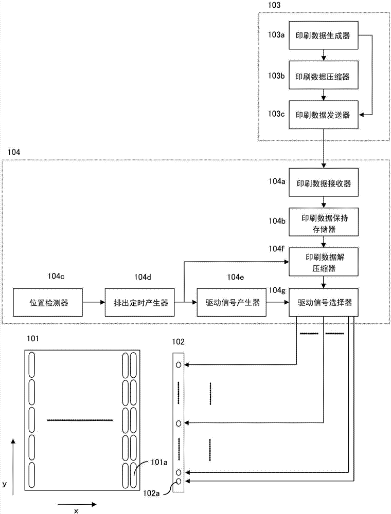
[0090] figure 1 It is a block diagram of the discharge circuit of the inkjet printing apparatus in Embodiment 1.

[0091] First, use figure 1 A block diagram of the inkjet printing device will be described.

[0092] There is a substrate 101 to be printed. There are banks 101 a (recesses) formed on the substrate 101 . The banks 101 a are arranged at constant pitches on the substrate 101 with respect to the printing scanning direction x. The print scan direction x is the direction in which the substrate 101 and the inkjet head 102 move relative to each other.

[0093] One or a plurality of inkjet heads 102 are arranged in a row in a direction y perpendicular to the printing scanning direction x. The inkjet head 102 has a plurality of nozzles 102a. The plu...

Embodiment approach 2

[0191] Embodiment 2 is a case where the output image is compressed for each line using the compression method of Embodiment 1. Items not described are the same as those in Embodiment 1.

[0192] Next, use Figure 11 (a)~ Figure 11 (c) for illustration.

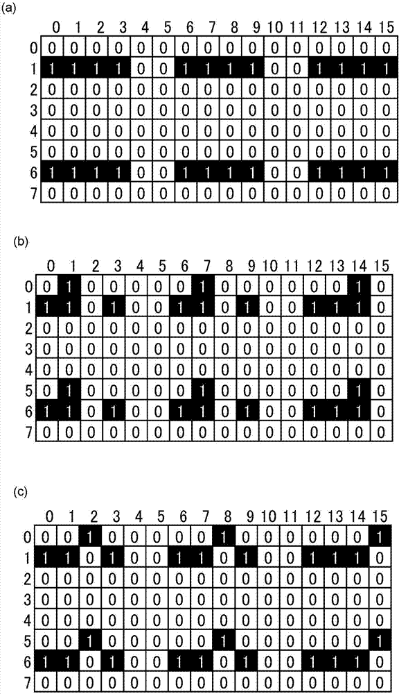
[0193] Figure 11 (a)~ Figure 11 (c) is to use the image compression method of embodiment 2, that is, the Put Bits compression pair image 3 (a)~ image 3 (c) Data in the case of compression, and image 3 (a)~ image 3 (c) likewise, Figure 11 (a) It becomes the print data before nozzle addition / position deviation correction, Figure 11 (b) become the print data after nozzle addition, Figure 11 (c) becomes the print data after positional deviation correction. about Figure 11 (a)~ Figure 11 (c) is described as a one-dimensional sequence, and superscripts on the data indicate sequence numbers.

[0194] In addition, here, it is assumed that the compression process is performed sequentially from the upper left o...

Embodiment approach 3

[0219] A method at the time of printing when compression is performed by the compression methods of Embodiments 1 and 2 will be described as Embodiment 3. Matters not described are the same as those in Embodiments 1 and 2.

[0220] In this way, in Put Bits compression, which is the image compression method of Embodiments 1 and 2, the data length does not change even if nozzle addition or positional deviation correction is performed. Therefore, even when nozzle addition or positional deviation correction is performed, it is not necessary to recompress all the data again, and it can be dealt with only by changing a part of the correction.

[0221] exist Figure 12 (a), Figure 12 (b) shows the operation of the inkjet printer when Put Bits compression, which is the image compression method of Embodiments 1 and 2, is used. Figure 12 (a) is the operation flow at the time of initial printing, Figure 12 (b) is the operation at the time of non-ejection supplementation and positi...


PUM


Abstract

The invention provides a compression data structure, a printing data compression method using thesame and a printing method. During data printing, compressed data can be simply corrected. A compression structure containing the amount of drop discharge in the number of a plurality of drop discharge data, each position of a plurality of above-mentioned drop discharge data, and a position of each above is used. A print-data compression method includes a pause process of dividing print data which are the maps of discharge timing of a drop and a nozzle location which discharges the aforementioned drop for every fixed section, and a compression process of compressing the aforementioned print data of the above-mentioned fixed section into the above-mentioned compressed data structure is used.

Description

technical field [0001] The present invention relates to a compressed data structure, a print data compression method and a printing method using the compressed data structure. In particular, it relates to a compression data structure in the case of applying liquid droplets, and a print data compression method and printing method using the compression data structure. Background technique [0002] As a method of manufacturing devices such as color filters of liquid crystal displays and organic EL displays, there is a method using inkjet. That is, a method in which a liquid body containing a functional material is discharged as droplets from a plurality of nozzles for inkjet to form a film of the functional material on an object to be coated. [0003] With such an inkjet system, the discharge pattern is handled as print data. The above-mentioned print data to be used is switched according to the batch switching of the object to be coated and the change of the state of the noz...

Claims


Application Information

Patent Timeline
IPC IPC(8): H03M7/46B41M5/00
CPCB41M5/0047H03M7/46
Inventor 增永圭二郎田中彰一
Owner PANASONIC INTELLECTUAL PROPERTY MANAGEMENT CO LTD
Why Eureka
Try Eureka