

Resource allocation method, network side equipment and terminal
A technology for network-side equipment and resource allocation, applied in the directions of network traffic/resource management, electrical components, wireless communication, etc., can solve problems such as no effective solution, shorten the request time, reduce the request process, and reduce the control signaling overhead Effect
- Summary
- Abstract
- Description
- Claims
- Application Information
AI Technical Summary
Problems solved by technology
Method used
Image


Examples
Embodiment 1
[0072] An embodiment of the present invention provides a resource configuration method. figure 2 It is a schematic flowchart of a resource allocation method in Embodiment 1 of the present invention; figure 2 As shown, the resource allocation method includes:
[0073] Step 201: The network side device allocates uplink resources for low-latency services through configuration or reservation.
[0074] In this embodiment, the network side equipment includes at least one of the following equipment: evolved base station (eNB), relay station (RN), cell coordination entity (MCE), gateway (GW), mobility management equipment (MME) , an Evolved Universal Terrestrial Radio Access Network (EUTRAN) Operations Administration and Maintenance (OAM) manager, etc., in each embodiment of the present invention, an eNB is used as a network side device as an example for illustration.
[0075] Here, the network-side device allocates the uplink resources of the low-latency service through configura...
Embodiment 2
[0090] The embodiment of the present invention also provides a resource configuration method. Figure 4 It is a schematic flowchart of a resource allocation method in Embodiment 2 of the present invention; Figure 4 As shown, the method includes:
[0091] Step 301: After receiving the trigger indication of the low-latency service, the terminal searches for and obtains uplink scheduling information.
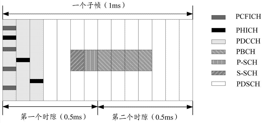
[0092] Here, the searching and obtaining the uplink scheduling information includes: searching the common search space of the PDCCH, or the specific search space of the terminal, or the dedicated search space of the low-delay service to obtain the uplink scheduling information.
[0093] The dedicated search space for the low-delay service may be specific positions on a specific symbol.
[0094] Wherein, before obtaining the uplink scheduling information, the method further includes: the terminal obtains a preset identifier through a broadcast message; or obtains a preset identif...
Embodiment 3
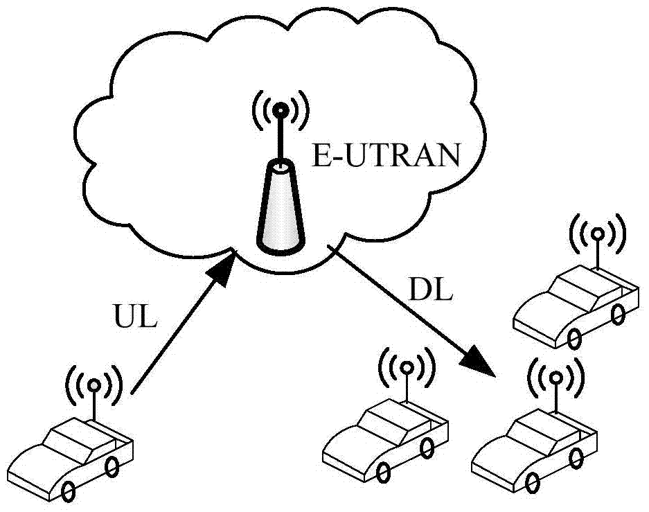
[0103] The embodiment of the present invention also provides a resource configuration method. In this embodiment, the V2X terminal transmits information based on the uplink resources pre-configured by the base station and based on the Uu link (that is, the link from the Vehicle to the eNodeB).
[0104] In a nutshell, first of all. The base station sends pre-configured related information, and the pre-configured related information can be carried by the PDCCH, where the format of the PDCCH can be format0, format4, or a newly added format formatX, and for the PDCCH carrying specific information, it adopts a predefined V-RNTI is scrambled, and V-RNTI notifies V2X terminals within the coverage area through broadcast messages; or it can be sent to V2X terminals through RRC signaling when the base station establishes a V2X link with V2X terminals; or it can be pre-configured in a predefined way. Then the V2X terminal receives the preconfigured related information. The preconfigure...
PUM
 Abstract
Description
Claims
Application Information