Load current regulation circuit and regulation method

A technology of load current and adjusting circuit, applied in the field of electronics, can solve the problems of increasing the influence of the OP0 error of the operational amplifier, the limitation of the frequency range of the pulse signal PWM, the limitation of the frequency of the pulse signal PWM, etc.

Active Publication Date: 2017-08-08
NANJING SILERGY SEMICON TECH CO LTD
View PDF7 Cites 9 Cited by
  • Summary
  • Abstract
  • Description
  • Claims
  • Application Information

AI Technical Summary

Problems solved by technology

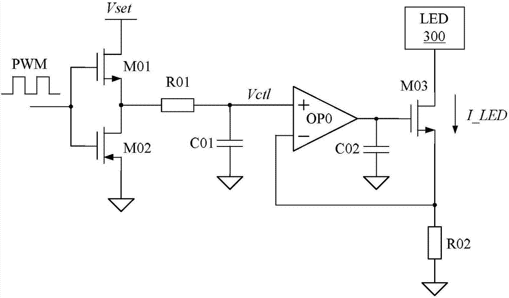
[0004] However, the disadvantage of this method is that when the frequency of the pulse signal PWM signal is small, it is necessary to increase the corresponding time constant (resistor R01 × capacitor C01) to achieve a better filtering effect, that is, to achieve a smaller analog dimming signal The ripple of Vctl makes the analog dimming signal Vref approximate a DC voltage
However, in general, the resistance area and capacitance area cannot be made large inside the chip, so when there is no external filtering, the frequency of the pulse signal PWM will be severely limited
In addition, when the LED load current I_LED obtained by the above method decreases with the duty cycle D_pwm, Vctl=Vset×D_pwm will also decrease, and when the duty cycle D_pwm decreases to a very small value, the amplitude of the dimming signal Vctl will also be small, resulting in a significant increase in the effect of errors due to the offset voltage of the operational amplifier OP0
In summary, this method limits the frequency range of the pulse signal PWM

Method used


Image

  • Load current regulation circuit and regulation method
  • Load current regulation circuit and regulation method
  • Load current regulation circuit and regulation method

Examples


Embodiment Construction

[0046] The present invention is described below based on the embodiments, and many specific details of the present invention are described below for a clearer understanding of the present invention. However, as will be appreciated by those skilled in the art, the invention may be practiced without these specific details, ie, the invention is not limited to these embodiments. In order not to obscure the essence of the present invention, well-known methods, procedures, procedures, components and circuits have not been described in detail.

[0047] Like elements are indicated with like reference numerals in the various figures. Additionally, those of ordinary skill in the art will appreciate that the drawings provided herein are for illustrative purposes and are not necessarily drawn to scale.

[0048] Meanwhile, it should be understood that in the following description, "circuit" refers to a conductive loop formed by at least one element or sub-circuit through electrical connec...


PUM


Abstract

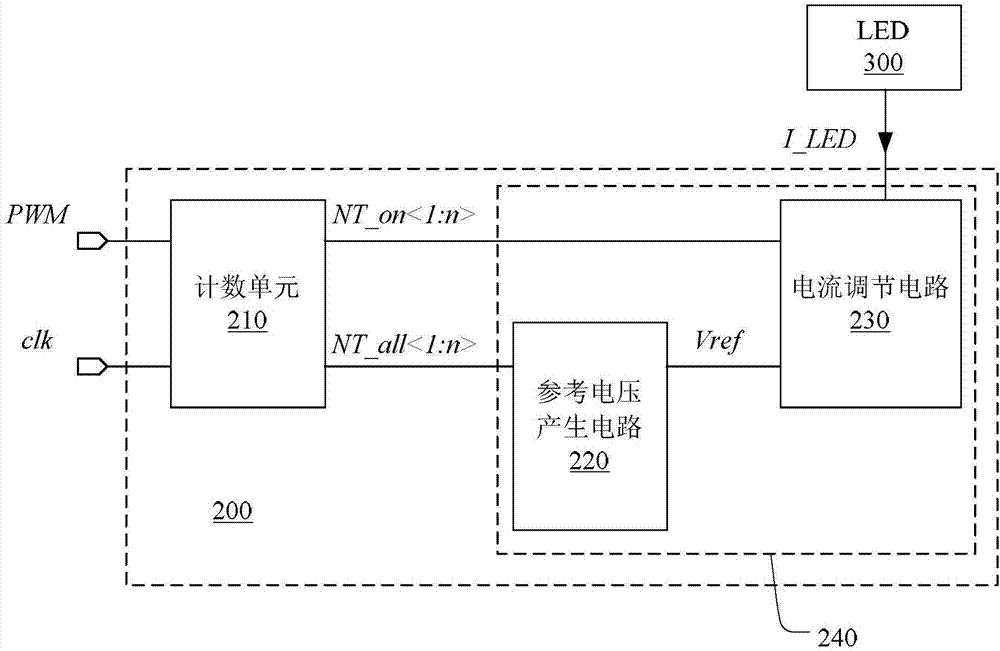
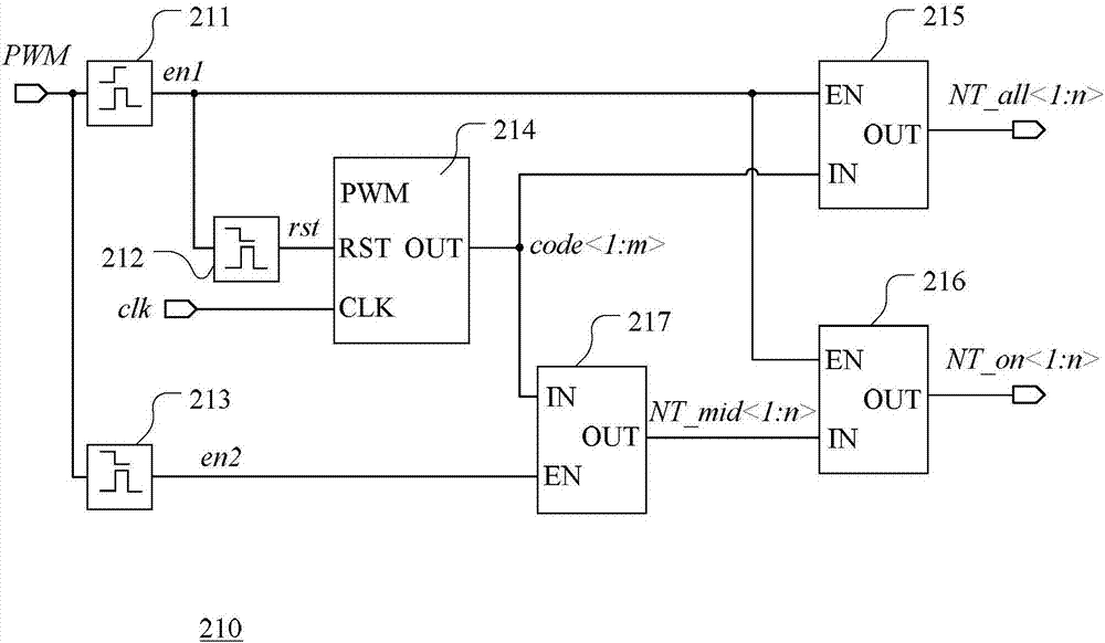
The invention discloses a load current regulation circuit and regulation method. The load current regulation circuit comprises a counting unit and a regulation unit, wherein the counting unit is used for generating a first digital signal and a second digital signal according to a pulse signal, a relation between the first digital signal and the second digital signal is determined according to a duty ratio of the pulse signal, and the regulation unit is used for regulating a load current according to the first digital signal and the second digital signal so that the load current changes with the duty ratio of the pulse signal. With the load current regulation circuit and the regulation method, provided by the invention, the chip area can be saved, the cost is reduced, an error brought by an offset voltage is avoided, so that high-accuracy regulation of the load current within a wide frequency range of the pulse signal is achieved.

Description

technical field [0001] The present invention relates to the field of electronic technology, and more specifically, to a load current regulating circuit and a regulating method. Background technique [0002] Light Emitting Diode (LED) has become a new generation of green light source due to its long life, high luminous efficiency, and environmental friendliness. At present, LED not only replaces ordinary existing light sources in the traditional lighting field, but also is gradually applied in some fields that require high dimming, such as backlighting in Liquid Crystal Display (LCD). When designing the load current regulation circuit of the LED, it is necessary to realize the dimming of the LED by changing the load current flowing through the LED. [0003] The existing technology generally adopts the method of analog dimming to adjust the brightness of the LED, such as using a passive filter to filter the pulse signal PWM into a DC signal, so as to obtain the analog dimming...

Claims


Application Information

Patent Timeline
Patent Type & Authority Applications(China)
IPC IPC(8): H05B33/08H05B44/00
CPCH05B45/395H05B45/10H05B45/325Y02B20/30H02M3/33515H02M1/08H05B41/282
Inventor 于利民
Owner NANJING SILERGY SEMICON TECH CO LTD
Why Eureka
Try Eureka