
Server functional wind shield

A windshield, functional technology, applied in cooling/ventilation/heating retrofit, circuit layout on support structures, electrical components, etc. Stability, inability to effectively control wind speed and wind direction, etc., to save structural space, meet the needs of cooling and heat dissipation, and avoid negative effects

Inactive Publication Date: 2017-08-08
ZHENGZHOU YUNHAI INFORMATION TECH CO LTD
View PDF5 Cites 0 Cited by
  • Summary
  • Abstract
  • Description
  • Claims
  • Application Information

AI Technical Summary

Problems solved by technology

[0003] Most of the windshields used inside the servers are relatively simple, and most of them are straight rectifiers, which cannot effectively control the wind speed and direction, and cannot centrally dissipate heat from the CPU or other core components, resulting in low fan efficiency. , unable to meet the heat dissipation and cooling requirements inside the machine, which seriously affects the working efficiency and operation stability of the cabinet

Method used


Image

  • Server functional wind shield
  • Server functional wind shield
  • Server functional wind shield

Examples


Embodiment 1

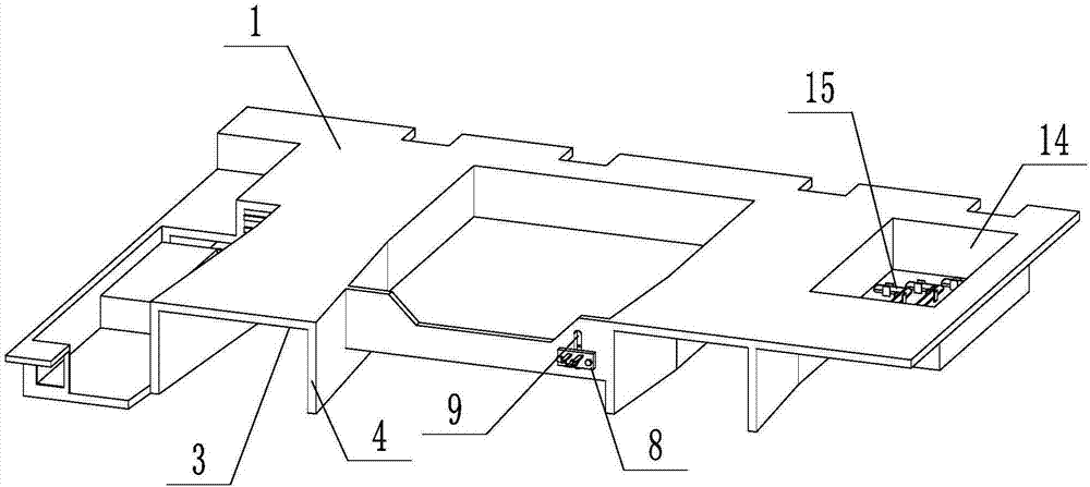
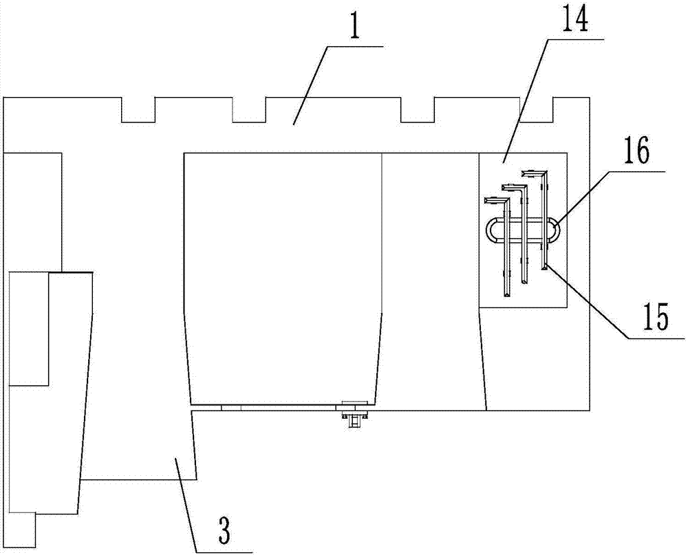
[0036] according to Figure 1 to Figure 6 As shown, a server functional windshield includes a windshield cover body 1 and two wind speed channels 2, the air inlet of the wind speed channel 2 is provided with a bell mouth 3, and the two wind speed channels 2 are respectively located on two CPUs. workspace and three memory workspaces;

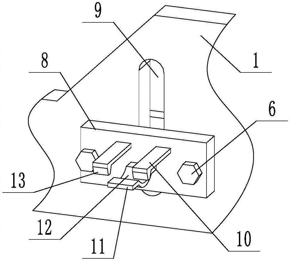
[0037] The outer surface of the windshield cover body 1 is provided with a wire harness fixing clip, and the wire harness fixing clip is movably connected to the windshield cover body 1 through an adjustment device;

[0038] The right side of the windshield cover body 1 is provided with a tool fixing groove 14, and the tool fixing groove 14 is provided with a maintenance tool 15, and the maintenance tool 15 is fixed in the tool fixing groove 14 by a fixing device, and the bottom surface of the tool fixing groove 14 is provided with a long circular groove 16. On the right side of the windshield, there is a clip slot for fixing maintenance tools,...

Embodiment 2

[0048] according to Figure 7 and Figure 8 As shown, the fixing device can also adopt a spring fixing method, including a compression housing 23 and a compression spring 22. There are two compression housings 23, which are left and right symmetrical. Sheet 26, upper slider 24 and lower slider 25, the compression housing 23 and the tool fixing groove 14 are slidably connected; the compression spring 22 is provided with two, respectively located on the outside of the compression housing 23, to compress The spring 22 is respectively connected with the pressing housing 23 and the tool fixing groove 14 .

[0049] The inner sides of the compression pieces 26 on the left and right compression housings 23 are respectively provided with grooves III 29, and the two grooves III 29 cooperate to form a circle, and the two grooves III 29 cooperate to form a circle to play a positioning role for the maintenance tool 15. Other fixing devices on the same maintenance tool 15 work together to...


PUM


Abstract

A server functional windshield disclosed by the present invention includes a windshield cover body and two wind speed channels, the air inlet of the wind speed channel is provided with a bell mouth, and the two wind speed channels are respectively located in two CPU work areas and three wind speed channels. A memory work area; the outer surface of the windshield cover is provided with a wire harness fixing clip, and the wire harness fixing clip and the windshield cover are flexibly connected by an adjustment device; the right side of the windshield cover is provided with a tool fixing slot , the tool fixing groove is provided with a maintenance tool, the maintenance tool is fixed in the tool fixing groove through a fixing device, and the bottom end surface of the tool fixing groove is provided with a long circular groove. There is a bell mouth at the air inlet of the wind speed channel, so that the air intake at the fan end is more sufficient, and the air flow through the CPU radiator and memory is faster, which can dissipate the heat generated when the machine is working in time, and maintain the internal work of the machine Stability of the environment.

Description

technical field [0001] The invention relates to the technical field of cloud server structure heat dissipation, in particular to a server-functional windshield. Background technique [0002] With the continuous innovation of server technology, the performance requirements are getting higher and higher. In the face of increasingly large data processing and high-performance CPU processors, a good heat dissipation system and structure are particularly important. Therefore, higher requirements should be put forward for the cooling performance of the network server. [0003] Most of the windshields used inside the servers are relatively simple, and most of them are straight rectifiers, which cannot effectively control the wind speed and direction, and cannot centrally dissipate heat from the CPU or other core components, resulting in low fan efficiency. , unable to meet the heat dissipation and cooling requirements inside the machine, which seriously affects the working efficie...

Claims


Application Information

Patent Timeline
Patent Type & Authority Applications(China)
IPC IPC(8): H05K7/20H05K7/12
CPCH05K7/20718H05K7/12H05K7/20145
Inventor 张洪镇肖波李松磊
Owner ZHENGZHOU YUNHAI INFORMATION TECH CO LTD
Learn More