
Circular pipe butt joint welding test rotating device and operation method thereof

A technology of welding test and rotating device, applied in the field of steel structure, can solve the problems of poor use effect and complex structure.

Active Publication Date: 2017-08-11
浙江东南网架股份有限公司 +1
View PDF8 Cites 1 Cited by
  • Summary
  • Abstract
  • Description
  • Claims
  • Application Information

AI Technical Summary

Problems solved by technology

This structure is relatively complicated, and the use effect is not good

Method used


Image

  • Circular pipe butt joint welding test rotating device and operation method thereof
  • Circular pipe butt joint welding test rotating device and operation method thereof
  • Circular pipe butt joint welding test rotating device and operation method thereof

Examples


Embodiment 1

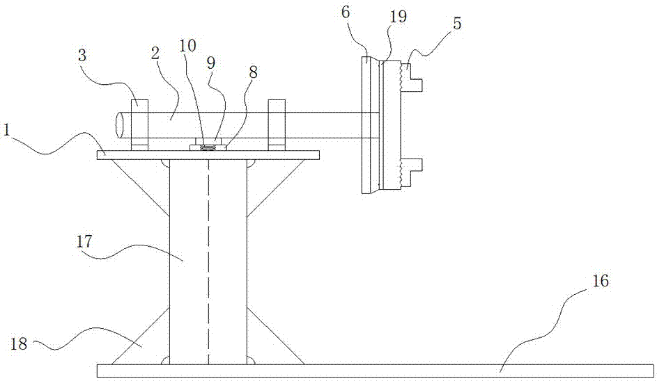
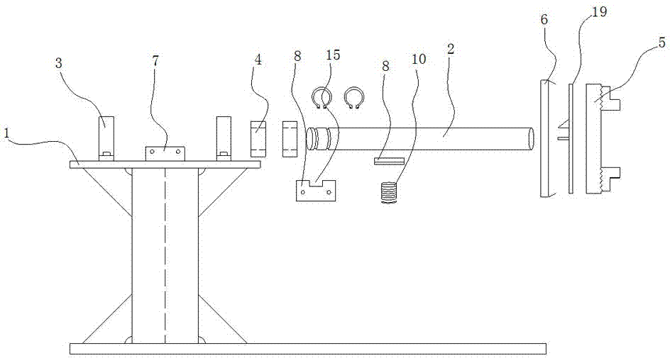
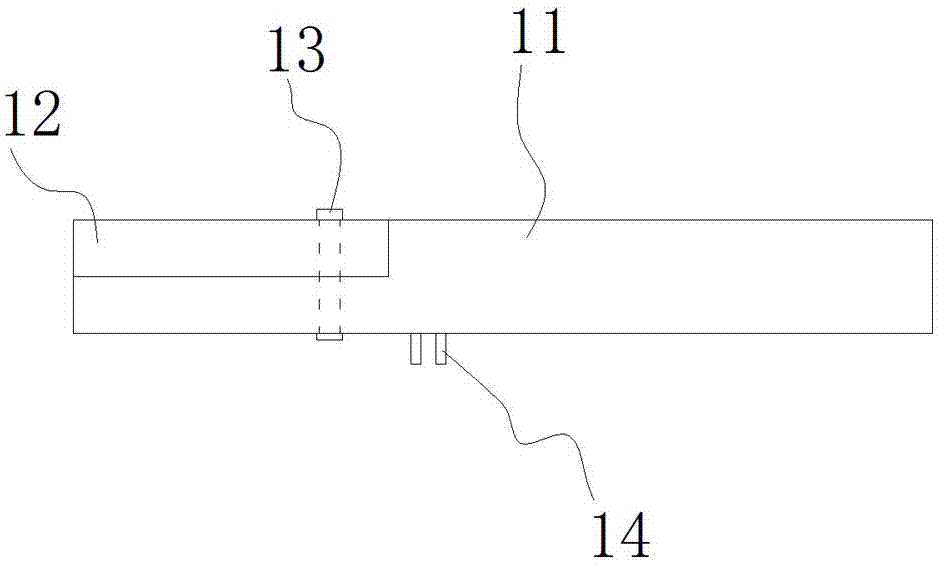
[0035] Embodiment 1: as figure 1 , figure 2 and image 3 As shown, a circular pipe butt welding test rotating device includes a base assembly and an operating platform assembly, and the upper part of the base assembly is provided with an operating platform assembly;

[0036] The operating platform assembly includes a platform 1, and a horizontally distributed shaft 2 is arranged on the top of the platform 1, and the shaft 2 is movable and positioned with the platform 1 through a pair of spaced apart bearing seats 3, A bearing 4 is provided between the bearing seat 3 and the shaft 2, and a welding manual chuck 5 is provided at the outer end of the shaft 2, and the welding manual chuck 5 drives the shaft 2 to rotate by turning the hand wheel 6.

[0037] The table 1 is provided with a fixed plate 7, the fixed plate 7 is provided with an insulating plate 8, and the upper part of the insulating plate 8 is provided with a grounding plate 9 in contact with the shaft 2. A spring 1...


PUM


Abstract

The invention relates to a test rotating device, in particular to a circular pipe butt joint welding test rotating device and an operation method thereof, and belongs to the field of steel structures. The device comprises a base module and an operation platform module; and the operation platform module is arranged at the upper part of the base module. The circular pipe butt joint welding test rotating device and the operation method thereof are compact in structure, and further improve the welding process through simulation assessment.

Description

technical field [0001] The invention relates to a test rotating device, in particular to a circular pipe butt welding test rotating device and an operating method thereof, belonging to the field of steel structures. Background technique [0002] During the welding procedure qualification test, some round steel pipe butt welding tests are often carried out, and round pipe butt joints often use rotational welding. At this stage, there is no corresponding tooling to support the welding test, which cannot meet the current needs. [0003] Chinese patent 201010586111.7 discloses a submerged arc automatic welding tool for a spherical segmented head. The welding tool 1 is composed of two runners, a worktable, and eight sets of fixed splints; the two runners are respectively fixed on the At both ends of the workbench, the eight sets of fixed splints are symmetrically arranged on the upper and lower planes of the workbench close to the runner, and the thickness H of the workbench is e...

Claims


Application Information

Patent Timeline
Patent Type & Authority Applications(China)
IPC IPC(8): B23K37/053
CPCB23K37/0533
Inventor 周观根吴志新杨弘生游桂模徐素芳邱麟鹏吴国华朱卫锋
Owner 浙江东南网架股份有限公司
Learn More