A fully automatic feeding and cutting machine

A material cutting machine and automatic feeding technology, applied in the field of mechanical processing, can solve the problems of difficult control of processing accuracy, inability to meet mass production, increase labor intensity of workers, etc., to improve cutting accuracy and production efficiency, and reduce labor intensity , the effect of improving production efficiency

Active Publication Date: 2018-12-21
湖南省鑫塔机械制造有限公司
View PDF6 Cites 2 Cited by
  • Summary
  • Abstract
  • Description
  • Claims
  • Application Information

AI Technical Summary

Problems solved by technology

[0002] Traditional cutting machines for rod / tubular materials need to install and fix the rod / tubular materials manually during the actual processing process. After the cutting machine cuts off one end of the rod / tubular materials, the rod / tubular materials need to be reinstalled Adjusting the position for secondary cutting, such a method of fixing→cutting→fixing→cutting→fixing... increases the labor intensity of workers, not only reduces production efficiency, but also makes it difficult to control the processing accuracy, which cannot meet the needs of mass production.

Method used


Image

  • A fully automatic feeding and cutting machine
  • A fully automatic feeding and cutting machine
  • A fully automatic feeding and cutting machine

Examples


Embodiment Construction

[0029] In order to enable those skilled in the art to better understand the technical solution of the present invention, the present invention will be described in detail below in conjunction with the accompanying drawings. The description in this part is only exemplary and explanatory, and should not have any limiting effect on the protection scope of the present invention. .

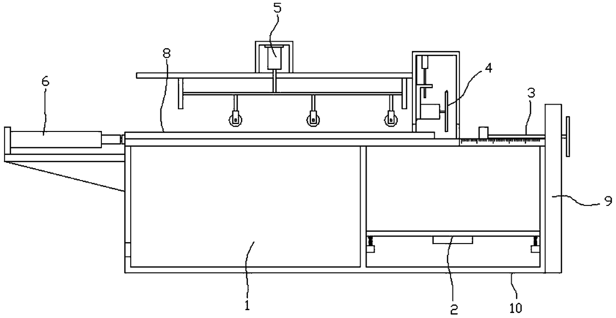
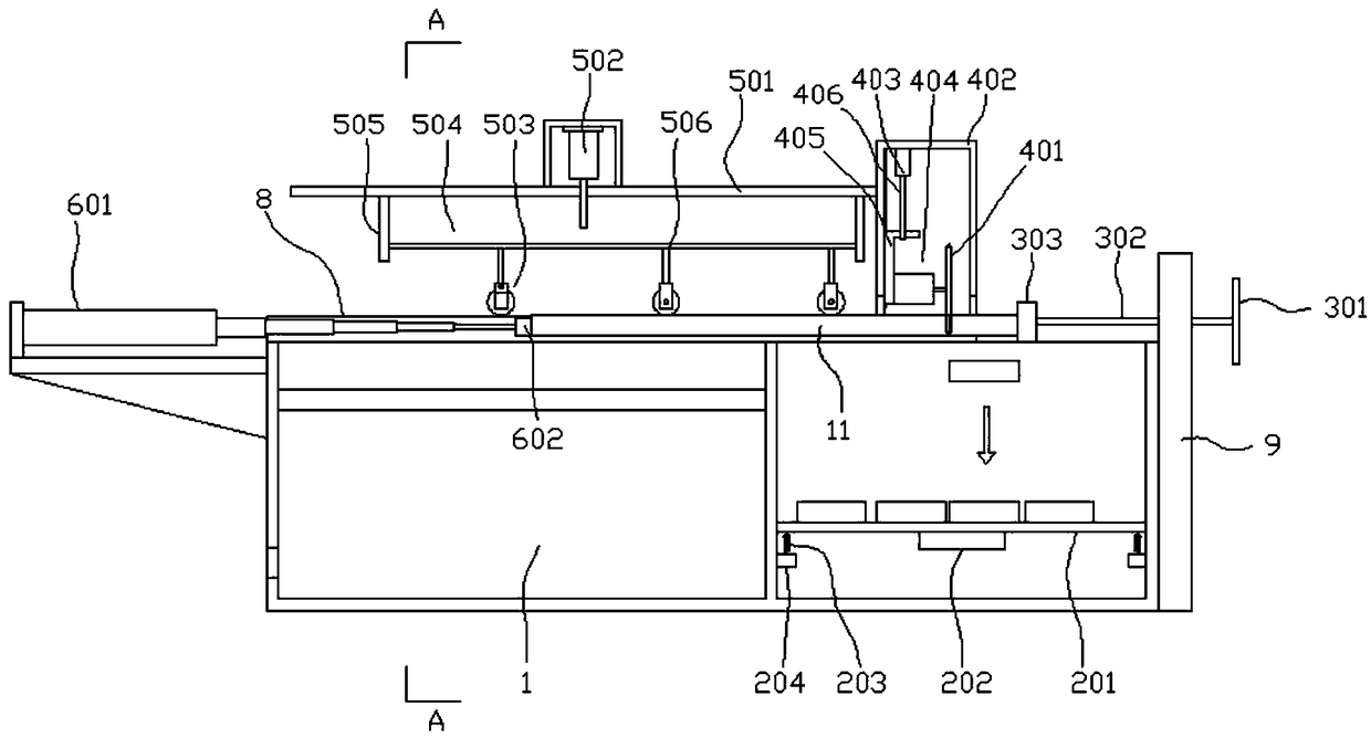
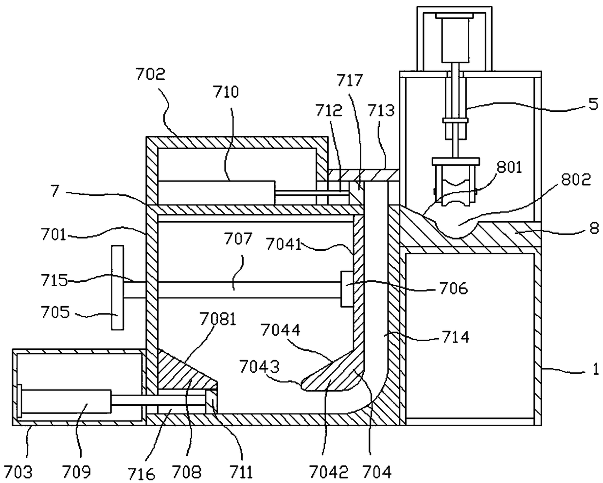
[0030] Such as Figure 1-Figure 6 As shown, the specific structure of the present invention is: it comprises frame 1, and its front end is provided with automatic feeding mechanism 7; The right side of described frame 1 is provided with material storage box 10; Described frame 1 and material storage The upper end of putting case 10 is provided with workbench 8; The left end of described workbench 8 is provided with pusher mechanism 6; The right end of described workbench 8 is provided with cutting mechanism 4 and material positioning mechanism 3; The upper end of described workbench 8 Correspondingly,...


PUM


Abstract

The invention discloses a full-automatic material feeding cutting machine which comprises a stand, wherein an automatic material feeding mechanism is arranged at the front end of the stand; a material storage tank is arranged on the right side of the stand; a working table is arranged at the upper ends of the stand and the material storage tank; a material pushing mechanism is arranged at the left end of the working table; a cutting mechanism and a material locating mechanism are arranged at the right end of the working table; a material pressing mechanism is correspondingly arranged at the upper end of the working table; the cutting mechanism and the material locating mechanism are arranged at the upper end of the material storage tank; the material locating mechanism is arranged at the right end of the cutting mechanism; an opening through which a material automatically falls is formed in a position, which corresponds to the lower ends of the cutting mechanism and the material locating mechanism, on the material storage tank; and a scrap removing mechanism is arranged inside the material storage tank. The full-automatic material feeding cutting machine can realize functions of automatic pushing, automatic locating and installation, automatic cutting, automatic storage and automatic scrap cleaning of rodlike / tubular materials, so that the cutting precision and the production efficiency are improved, the labor intensity of a worker is reduced, and the demand for large-batch production is met.

Description

technical field [0001] The invention belongs to the field of mechanical processing, in particular to a fully automatic feeding and cutting machine. Background technique [0002] Traditional cutting machines for rod / tubular materials need to install and fix the rod / tubular materials manually during the actual processing process. After the cutting machine cuts off one end of the rod / tubular materials, the rod / tubular materials need to be reinstalled Adjusting the position for secondary cutting, this method of back and forth fixing→cutting→fixing→cutting→fixing… increases the labor intensity of the workers, not only the production efficiency is low, but also the processing accuracy is difficult to control, which cannot meet the needs of mass production. Contents of the invention [0003] The purpose of the present invention is to address the above problems, to provide a fully automatic feeding cutting machine, which can realize the functions of automatic pushing, automatic po...

Claims


Application Information

Patent Timeline
Patent Type & Authority Patents(China)
IPC IPC(8): B26D1/12B26D7/06B26D7/08B26D7/28B26D7/01
CPCB26D1/12B26D7/0608B26D7/088B26D7/28B26D2007/013
Inventor 伍哲薇阮梦倩伍亿众
Owner 湖南省鑫塔机械制造有限公司
Why Eureka
Try Eureka