Plate adhering and automatic-outputting device

An automatic output and sheet material technology, which is applied in the direction of paper/cardboard layered products, lamination devices, lamination, etc., can solve the problem of weak sheet bonding, no automatic output, and no continuous automatic feeding and other issues to achieve the effect of automatic output and enhanced bonding firmness

Active Publication Date: 2017-08-11
阜阳汇中芯自动化技术有限公司
View PDF9 Cites 4 Cited by
  • Summary
  • Abstract
  • Description
  • Claims
  • Application Information

AI Technical Summary

Problems solved by technology

[0006] The purpose of the present invention is to address the deficiencies of the prior art, by absorbing and suspending one of the boards, and then realizing the lamination of the lower board and the work by means of lifting, and using rollers to press on the board and output the material by friction. It is further compacted and thus overcomes the problems that the equipment does not have continuous automatic feeding, does not have automatic discharging after the lamination is completed, and the sheet metal lamination is not firm.

Method used


Image

  • Plate adhering and automatic-outputting device
  • Plate adhering and automatic-outputting device
  • Plate adhering and automatic-outputting device

Examples


Embodiment 1

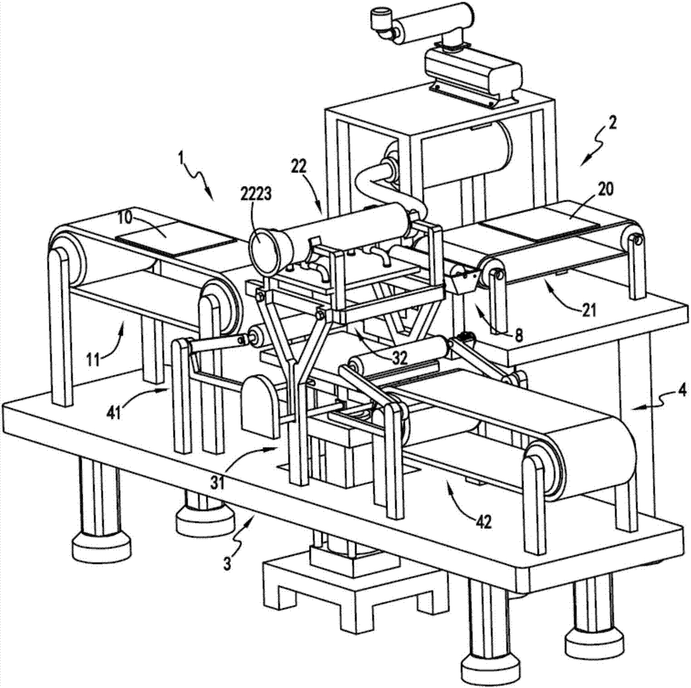
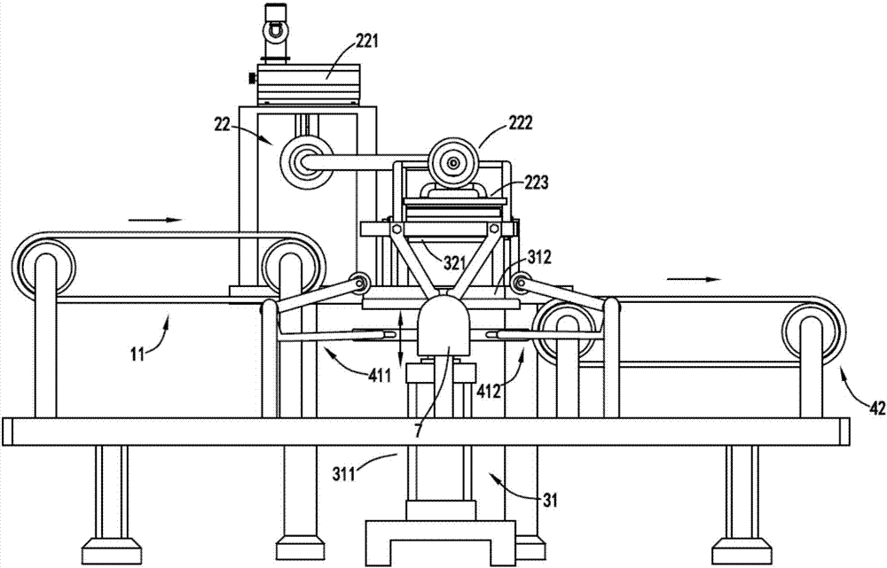
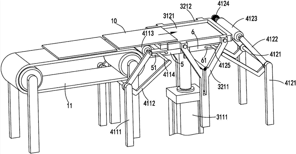
[0040] figure 1 It is a schematic diagram of the internal structure of the automatic output device after the plates are glued, figure 2 It is a schematic diagram of the front view of the automatic output equipment after the plates are glued, image 3 is a schematic diagram when the lower plate is transferred from the transfer mechanism a to the supporting device, Figure 4 It is a schematic diagram of the output of the composite board from the supporting device, Figure 5 It is a schematic diagram of the bonding of the lower plate and the upper plate, Figure 6 It is a schematic diagram of the structure when the support device moves to the output position after lamination, Figure 7 It is a schematic diagram of the structure of the conveying part of the upper plate, Figure 8 It is a cut-away schematic diagram of the negative pressure generating device and the negative pressure adsorption device, Figure 9 It is a schematic diagram when the pressing roller mechanism driv...

Embodiment 2

[0057] Such as figure 1 , figure 2 , image 3 , Figure 4 , Figure 5 , Figure 6 , Figure 7 , Figure 8 and Figure 9 As shown, the components that are the same as or corresponding to those in the first embodiment are marked with the corresponding reference numerals in the first embodiment. For the sake of simplicity, only the differences from the first embodiment will be described below. The difference between the second embodiment and the first embodiment is that, as a preference, a baffle 7 is also included, and the baffle 7 is fixed on the telescopic rod of the lifting cylinder 3111 through the fixing rod 71, driven by the lifting cylinder 3111 Performing lifting motion, the baffle plate 7 is used to block the outlet 2223 of the negative pressure generating device 222 when the upper plate 20 and the lower plate 10 are glued together.

[0058] The setting of the baffle plate 7 makes the lower plate 10 and the upper plate 20 stick together, and the negative pressu...


PUM


Abstract

The invention relates to a plate adhering and automatic-outputting device which comprises a lower plate conveying part, an upper plate conveying part, a lifting and adhering part and an output part. The lower plate conveying part is used for backwards outputting a lower plate. The upper plate conveying part is used for outwards outputting an upper plate, the lifting and adhering part is used for receiving the lower plate conveyed from the lower plate conveying part, driving the lower plate to upward move to be adhered with an upper plate of the upper plate conveying part and then driving the composite plate to move downward, and the output part is used for driving the composite plate on the lifting and adhering part to be output backward. The lower plate conveying part comprises a transmission mechanism a. The upper plate conveying part comprises a transmission mechanism b and a suction mechanism. The lifting and adhering part comprises a lifting mechanism and a positioning mechanism. The output part comprises compression roller mechanisms arranged on the front side and the rear side of the lifting mechanism and a transmission mechanism c. The problem that an existing device cannot perform continuous and automatic feeding and cannot achieve automatic discharging and makes plate adhesion infirm when adhesion is competed is solved.

Description

technical field [0001] The invention relates to the technical field of composite board production, in particular to a board material bonding and automatic output device. Background technique [0002] In order to prevent scratches or bruises during subsequent transportation, some sheets are often pasted with a layer of protective paper on their surface after processing. [0003] A Chinese utility model patent with the authorized announcement number CN202037959U, which discloses a film and sticker device on the sheet material uncoiling, leveling, and shearing production line, which accurately sends the sheet material, film tape or paper to the specified position through numerical control equipment Then use the film roller to stick the film, but the equipment has the following problems: [0004] 1. The equipment does not have the function of continuous automatic feeding of the two materials that need to be bonded together and synchronous output of the materials after the bondi...

Claims


Application Information

Patent Timeline
Patent Type & Authority Applications(China)
IPC IPC(8): B32B37/10B32B37/12B32B29/00
CPCB32B29/002B32B37/10B32B37/12
Inventor 丁伟平
Owner 阜阳汇中芯自动化技术有限公司
Why Eureka
Try Eureka