Eureka AIR delivers breakthrough ideas for toughest innovation challenges, trusted by R&D personnel around the world.

Tail rotor structure of unmanned helicopter

An unmanned helicopter and tail rotor technology, which is applied to unmanned aerial vehicles, rotorcraft, motor vehicles, etc., can solve problems such as poor balance performance, easily damaged steering blades, and difficulty in steering of unmanned helicopters, and improve the balance. , Enhanced balance performance, easy maintenance

Inactive Publication Date: 2017-08-11
BINZHOU UNIV
View PDF0 Cites 1 Cited by
  • Summary
  • Abstract
  • Description
  • Claims
  • Application Information

AI Technical Summary

Problems solved by technology

[0005] The purpose of the present invention is to provide a tail rotor structure of an unmanned helicopter to solve the problem of poor balance performance in the above-mentioned background technology, and at the same time, the steering blades are easily damaged by improper operation during the steering process, resulting in difficult steering of the unmanned helicopter.

Method used


Image

  • Tail rotor structure of unmanned helicopter
  • Tail rotor structure of unmanned helicopter
  • Tail rotor structure of unmanned helicopter

Examples


Embodiment Construction

[0023] Hereinafter, embodiments of the present invention will be described in detail, examples of which are shown in the drawings and the following description. Although the present invention will be described in conjunction with an exemplary embodiment, it should be understood that the description is not intended to limit the present invention to the exemplary embodiment. On the contrary, the present invention will not only cover the exemplary embodiment, but also various alternative, changed, equivalent and other embodiments, which may be included in the spirit and scope of the present invention defined by the appended claims Inside.

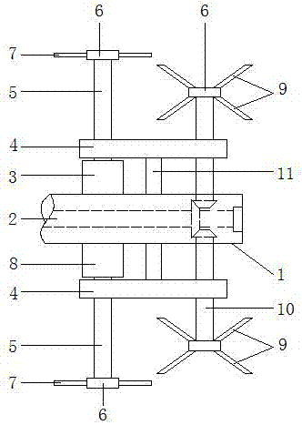
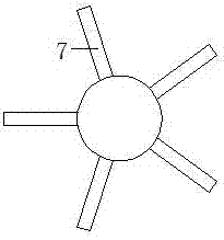
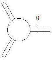
[0024] As attached figure 1 Attached Figure 4 , A tail rotor structure of an unmanned helicopter, including:

[0025] Fuselage tail part 1, main shaft 2, first micro steering motor 3, fixed plate 4, steering shaft 5, blade connecting sleeve 6, steering blade 7, second micro steering motor 8, balance blade 9, balance shaft 10 , Fix the connectin...


PUM


Abstract

The invention relates to a tail rotor structure of an unmanned helicopter. The tail rotor structure comprises a first miniature turning motor, turning blades, a second miniature turning motor, balancing blades and plastic bearings, wherein the first miniature turning motor and the second miniature turning motor are respectively fixedly mounted on the front and rear sides of a tail wing part of a helicopter body, and turning rotating shafts are connected to the front ends of the first miniature turning motor and the second miniature turning motor; the plastic bearings are embedded into two ends of a fixed plate; blade connecting sleeves are fixedly welded to the front end of the turning rotating shafts, and turning blades are welded to the outer sides of the blade connecting sleeves; and the blade connecting sleeves are further welded to the front end of a balancing rotating shaft, and the balancing blades are welded to the outer sides of the blade connecting sleeves. By symmetrically designing the balancing blades, the integral balance in a turning process is improved, and the controllability in the turning process is improved; and by setting two groups of turning motors, the situation that the turning is influenced when a group of turning tail rotors is failed is prevented.

Description

Technical field [0001] The invention relates to the technical field of an unmanned aerial vehicle matching tail rotor, in particular to a tail rotor structure of an unmanned helicopter. Background technique [0002] The structure of the unmanned helicopter is relatively simple, the price is relatively low, and it does not need a launch system at all. It can take off and land vertically, and can hover more freely. The flight flexibility is quite high. The air route is used for flying, so it is widely used in various fields such as military and civil. Unmanned helicopters are mainly composed of body and lift (including rotor and tail rotor), power, transmission three systems, and airborne flight equipment. The rotor is generally driven by a turboshaft engine or a piston engine through a mechanical transmission system composed of a drive shaft and a reducer. The main function of the tail rotor is to provide the reaction torque of the rotor, maintain the balance of the aircraft, an...

Claims


Application Information

Patent Timeline
Patent Type & Authority Applications(China)
IPC IPC(8): B64C27/82
CPCB64C27/82B64C2027/8227B64U10/10
Inventor 郭庆叶
Owner BINZHOU UNIV
Why Eureka
Eureka Blog
Learn More