drying system

A drying system and post-drying technology, applied in the field of drying systems, can solve the problems of longer drying time, slow heating speed, low energy efficiency, etc., and achieve the effect of shortening the required time

Active Publication Date: 2019-09-20
ZHEJIANG SANHUA INTELLIGENT CONTROLS CO LTD
View PDF4 Cites 0 Cited by
  • Summary
  • Abstract
  • Description
  • Claims
  • Application Information

AI Technical Summary

Problems solved by technology

The temperature rise rate of the above heat pump system is relatively slow to avoid damage to the clothes due to high temperature, which may lead to relatively longer drying time and relatively lower energy efficiency.

Method used


Image

  • drying system
  • drying system
  • drying system

Examples


Embodiment 1

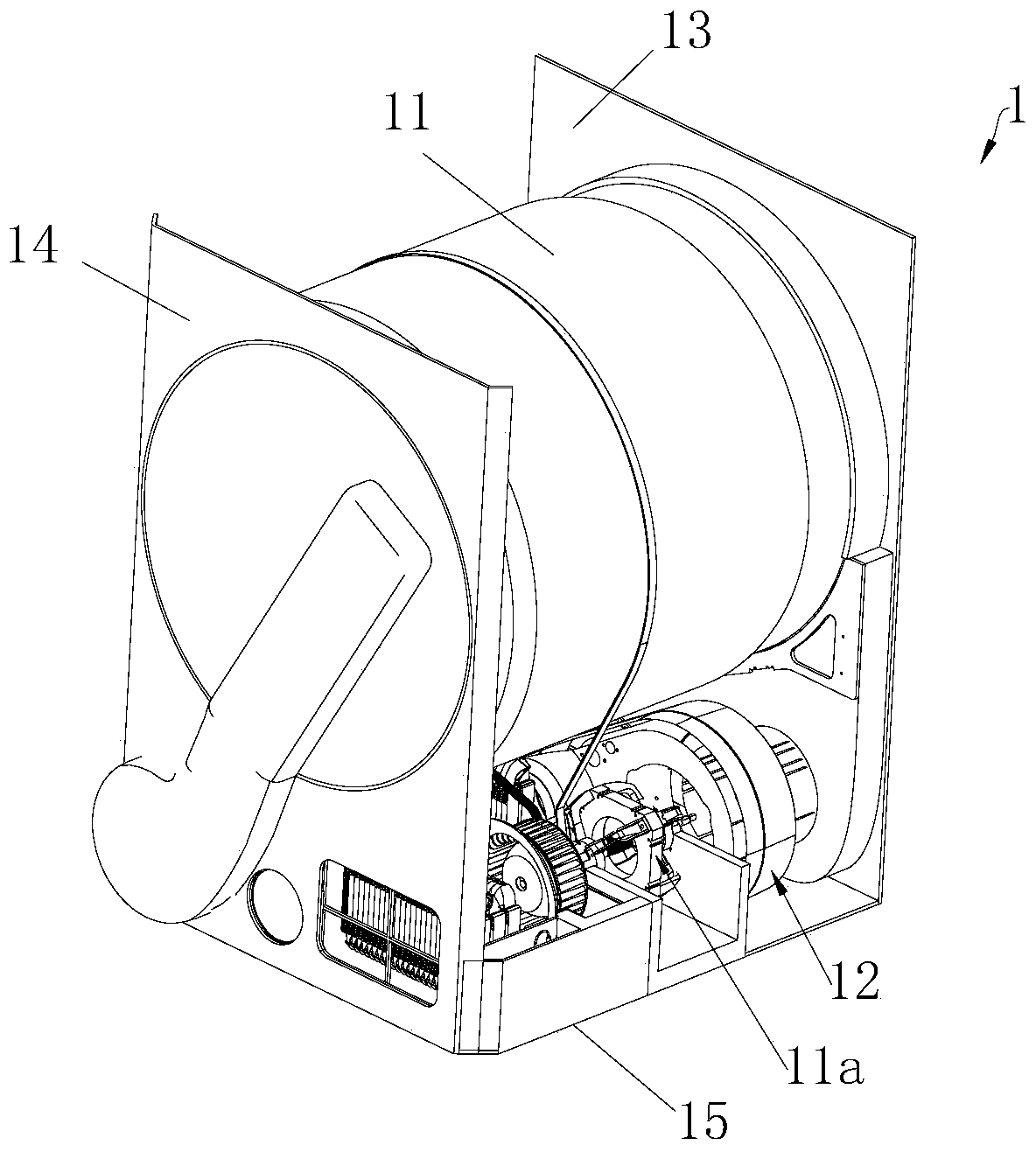
[0035] refer to Figure 1-4 In this embodiment, a drum is used as a drying container as an example for illustration. The clothes dryer 1 includes a cabinet, a drum 11 disposed inside the cabinet, a drying system 12, and a motor 11a for driving the drum 11 to rotate. The body includes a front wall portion 13, a rear wall portion 14 and a bottom 15, the front wall portion 13 is arranged opposite to the rear wall portion 14, the bottom 15 is defined as the space below the drum 11 of the above-mentioned box, and the drying system 12 Located at the bottom 15, the drum 11 is formed with a front side and a rear side correspondingly, and the box body is provided with an opening door for opening or closing the front side opening of the drum 11, and the front side of the drum 11 is assembled and connected with the front wall portion 13 of the box body, The rear side of the drum 11 is assembled and connected with the rear wall portion 14 of the box.

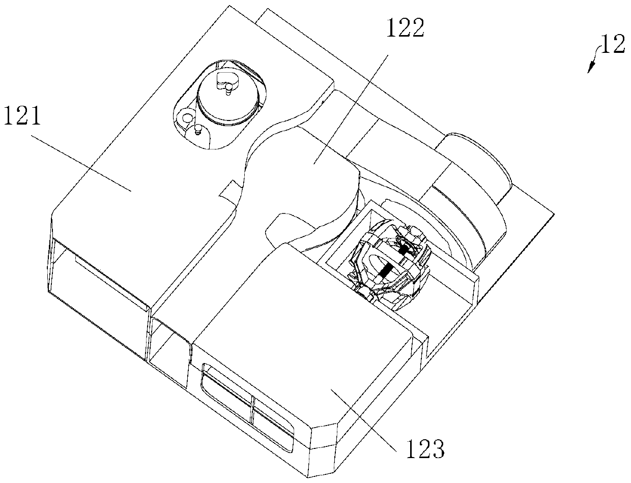
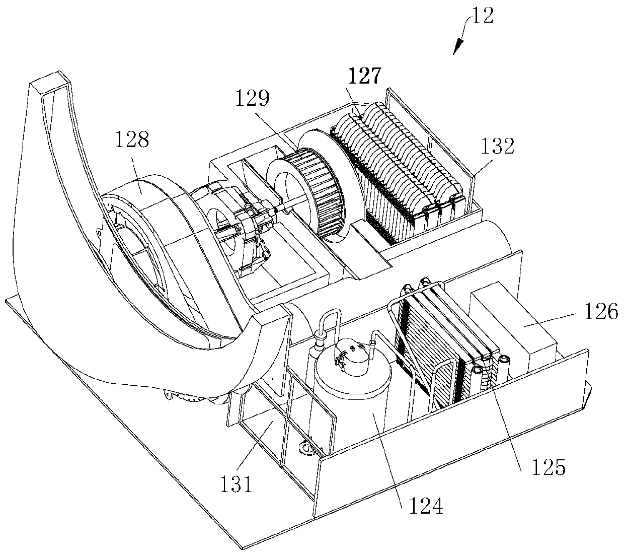
[0036]The drying system 12 includes...

Embodiment 2

[0046] refer to Figure 6 and Figure 8 , the drying system 12 of this embodiment is substantially the same as that of Embodiment 1, the difference is that the drying system 12 of this embodiment is also provided with a fourth heating device 133 in the air channel after drying, and the fourth heating device 133 is located between the first heating device 124 and the second heating device 125 , and reheats the air heated by the first heating device 124 .

[0047]The fourth heating device 133 of this embodiment includes a heat absorbing part and a heat releasing part, and heat transfer can be realized between the heat absorbing part and the heat releasing part; The heat is transferred to the heat release part; the heat release part is located in the air channel before drying, along the air flow channel extending direction of the air channel before drying, the heat release part is located between the first heating device 124 and the second heating device 125, and passes through ...

Embodiment 3

[0053] refer to Figure 7 and Figure 9 , the drying system of this embodiment is substantially the same as the drying system described in Embodiment 2, except that the fourth heating device 133' of this embodiment can be, for example, a heat pipe heat exchanger, and the heat pipe heat exchanger includes a heat pipe in a vacuum cavity , the heat pipe has a heat receiving section 133'a at one end and a heat releasing section 133'b at the other end, the heat receiving section 133'a is used as a heat absorbing part, and the heat releasing section 133'b is used as a heat releasing part; the inner wall of the heat pipe is provided with an absorbing Liquid core 133'c, the liquid-absorbing core 133'c is filled with working fluid, the outer wall of the heat pipe is provided with fins 133'd, and the working fluid absorbs the dried The heat of the air in the air channel is evaporated and condensed in the heat release section 133'b to heat the air in the air channel before drying. The ...


PUM


Abstract

The invention discloses a drying system comprising air channels. The air channels comprise a first air channel and a second air channel, and the first air channel is provided with a first air intake portion and a first air outlet portion. The drying system is successively provided with a first heating device, a second heating device and a third heating device in the first air channel in the air passage extension direction from the first air intake portion to the first air outlet portion, and the first, second and third heating devices are used for heating the air. The drying system is provided with a heat absorption device in the second air channel, and the heat absorption device is used for absorbing heat from the second air channel. The heat absorption device, the first heating device and the second heating device of the drying system form a refrigerant circulatory system, multistage heating of the intake air of the drying system is achieved, the air used for drying can be heated as quickly as possible, and the drying time is shortened.

Description

technical field [0001] The invention relates to the field of article drying, in particular to a drying system for drying articles such as clothes. Background technique [0002] According to whether the air flow path of the clothes dryer is closed, it is divided into a closed-loop system and an in-line system. Compared with closed-loop systems, direct drainage systems do not require water storage devices (such as water tanks) and drainage devices (such as water pumps). Clothes dryers are divided into electric heating systems and heat pump systems according to the heating source of the air entering the drum. [0003] The air direction of an existing clothes dryer with a direct-exhaust heat pump system is roughly that the air flows through the condenser and is heated to become high-temperature and low-humidity air, which is then sent into the drum to dry clothes, and the wet clothes can be gradually taken away. Moisture, and then discharge the air that comes out of the drum w...

Claims


Application Information

Patent Timeline
Patent Type & Authority Patents(China)
IPC IPC(8): D06F58/02D06F58/26D06F58/20
Inventor 不公告发明人
Owner ZHEJIANG SANHUA INTELLIGENT CONTROLS CO LTD
Why Eureka
Try Eureka