Two-section-type righting electric pole correction device

A correction device, a two-stage technology, applied in building types, buildings, towers, etc., can solve the problems of short strokes of safety hydraulic jacks, inconvenient daily life of residents, affecting power transmission, etc., to avoid safety accidents and avoid correction accuracy. Low, the effect of improving work efficiency

Inactive Publication Date: 2017-08-11
STATE GRID ZHEJIANG HANGZHOU YUHANG POWER SUPPLY +2
View PDF7 Cites 10 Cited by
  • Summary
  • Abstract
  • Description
  • Claims
  • Application Information

AI Technical Summary

Problems solved by technology

The above two methods are time-consuming, labor-intensive, low in safety, and require power outage construction, which affects power transmission, brings economic losses to enterprises, and brings inconvenience to residents' daily life.
The existing electric pole corrector directly uses the hydraulic jack to correct, the work is unstable, there are safety problems, the stroke of the hydraulic jack is short, etc.

Method used


Image

  • Two-section-type righting electric pole correction device
  • Two-section-type righting electric pole correction device
  • Two-section-type righting electric pole correction device

Examples


Embodiment 1

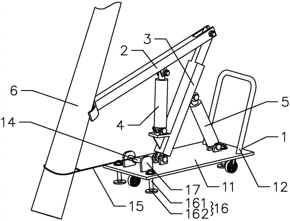
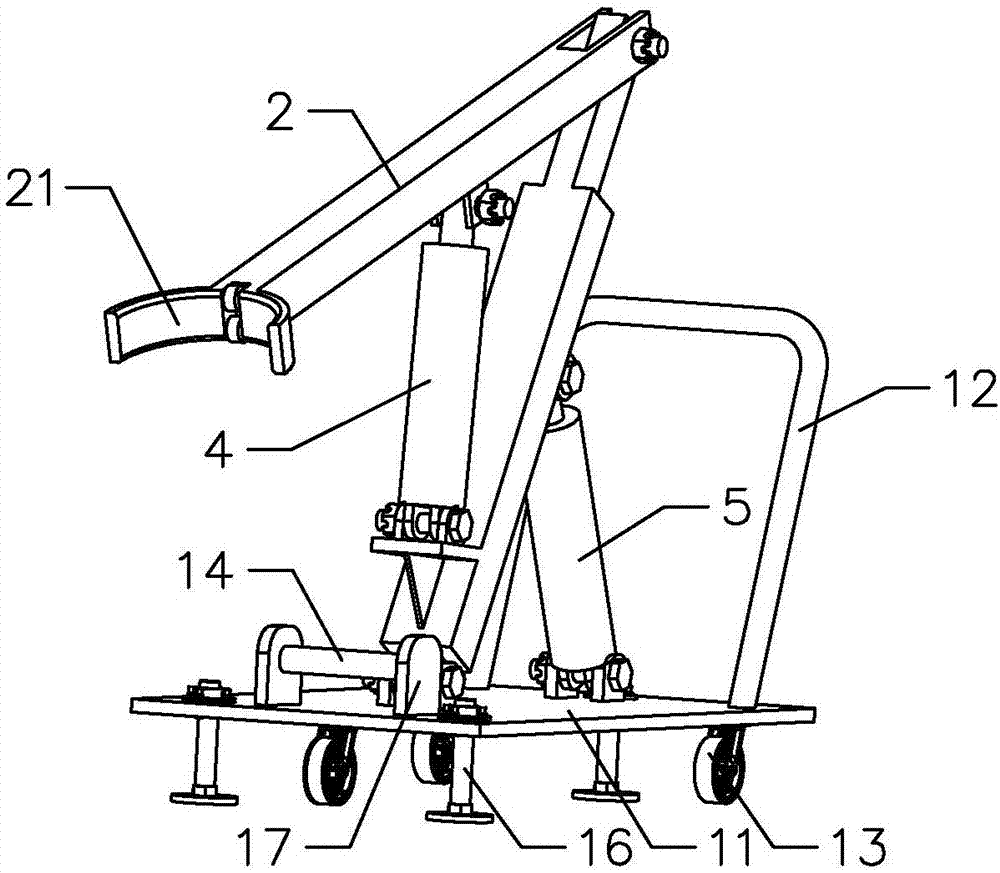
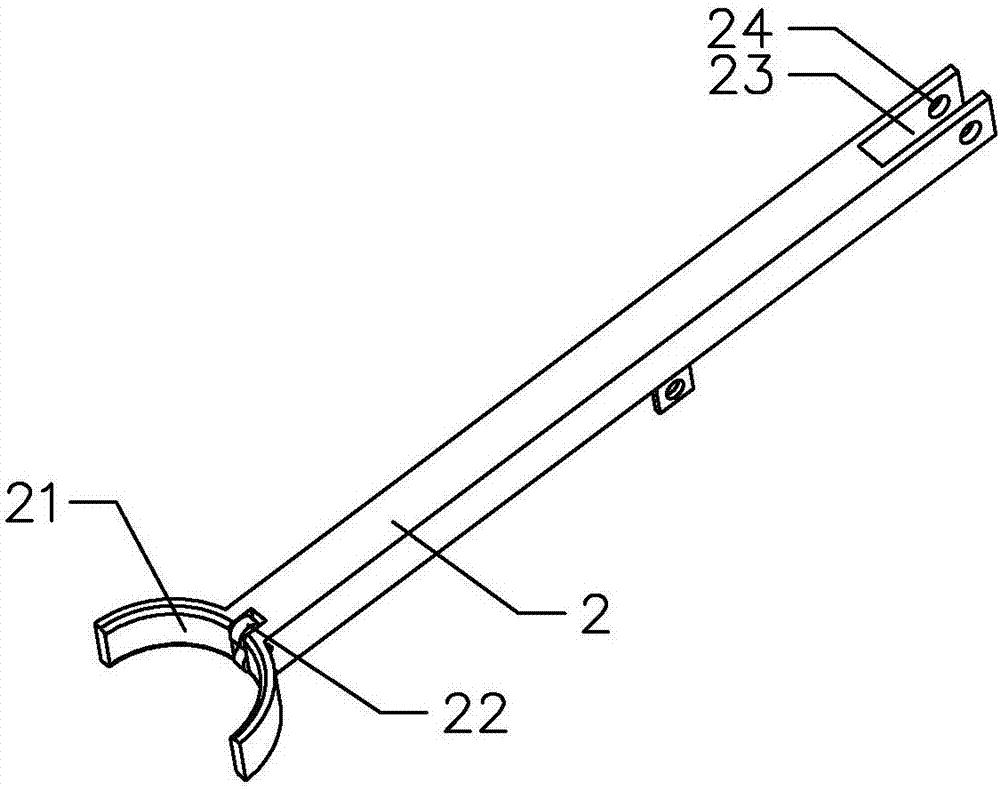
[0035] Such as Figures 1 to 5 As shown, the present invention provides a two-stage righting pole correction device, comprising a workbench 1, a first righting arm 2, a first jack 4 for pushing the first righting arm 2, a second righting arm 3 and a push The second jack 5 of the second righting arm 3, the bottom of the second righting arm 3 is fixed on the workbench 1, the top of the second righting arm 3 is rotationally connected with one end of the first righting arm 2, and the first righting arm 2 The other end of the pole 6 conflicts.

[0036]In this embodiment, the first jack 4 is operated to push the first righting arm 2 to realize the first section of righting of the electric pole 6, and the second jack 5 is operated to push the second righting arm 3, and the second righting arm 3 Promote the first righting arm 2 to realize the second stage righting of the electric pole 6, by setting the first righting arm and the second righting arm, and the first righting arm and the...

Embodiment 2

[0048] The difference between this embodiment and the first embodiment lies in that the shapes of the first righting arm and the second righting arm are different.

[0049] In this embodiment, both the first righting arm and the second righting arm are in the shape of a circular tube. The structures and beneficial effects of other parts not described are the same as those in Embodiment 1, and will not be repeated here.

Embodiment 3

[0051] The difference between this embodiment and the first and second embodiments is that the first righting arm is different.

[0052] In this embodiment, the first righting arm includes a fixed section and a telescopic section inserted in the fixed section. The telescopic section can be stretched and retracted in the fixed section to change the overall length of the first righting arm, further increasing the work of the electric pole correction device. The stroke further improves the scope of application of the pole correction device. The structures and beneficial effects of other parts not described are the same as those of Embodiments 1 and 2, and will not be repeated here.


PUM


Abstract

The invention provides a two-section-type righting electric pole correction device comprising a worktable, a first righting arm, a first jack pushing the first righting arm, a second righting arm and a second jack pushing the second righting arm. The bottom of the second righting arm is fixed on the worktable; the top of the second righting arm is rotationally connected with one end of the first righting arm, and the other end of the first righting arm abuts against an electric pole; the first jack is operated to push the first righting arm so as to achieve first-section righting of the electric pole; and the second jack is operated to push the second righting arm, and the second righting arm pushes the first righting arm to achieve second-section righting of the electric pole. The working stroke of the electric pole correction device is increased to remedy the defect of the short strokes of the jacks, and the application range of the electric pole correction device is widened; and by righting the electric pole for the two times, the accuracy of electric pole righting is improved, and the correction effect of the electric pole is guaranteed.

Description

technical field [0001] The invention relates to the technical field of electric pole correctors, in particular to a two-stage righting electric pole correcting device. Background technique [0002] Due to various reasons, the utility poles installed outdoors often have the problem of tilting the utility poles. The tilting of utility poles is one of the main causes of power grid blackout accidents, and it is also a major hidden danger that threatens personal safety. In the past, the straightening of utility poles relied entirely on manpower. The traditional correction methods for utility poles mainly include: (1) first fix the stay rope at the tip of the pole, and then use the manpower to directly pull the stay rope to straighten the utility pole; (2) directly push the utility pole with a push rod by manpower. The above two methods are time-consuming, labor-intensive, low in safety, and require power outage construction, which affects power transmission, brings economic los...

Claims


Application Information

Patent Timeline
Patent Type & Authority Applications(China)
IPC IPC(8): E04H12/34
CPCE04H12/345
Inventor 闫宝张烁陈超赖尚栋苏浩航
Owner STATE GRID ZHEJIANG HANGZHOU YUHANG POWER SUPPLY
Why Eureka
Try Eureka