Dual-threshold three-stable-state collision sensor
A collision sensor and tri-stable technology, applied in the field of dual-threshold tri-stable collision sensors, can solve the difficulty of judging the intensity of continuous collisions for more than two times, increase the cost of the sensor measurement system, and affect the response speed and reliability of the safety system. and other problems, to achieve the effect of high reliability, high threshold sensing accuracy and low cost
- Summary
- Abstract
- Description
- Claims
- Application Information
AI Technical Summary
Problems solved by technology
Method used
Image
Examples
Embodiment 1
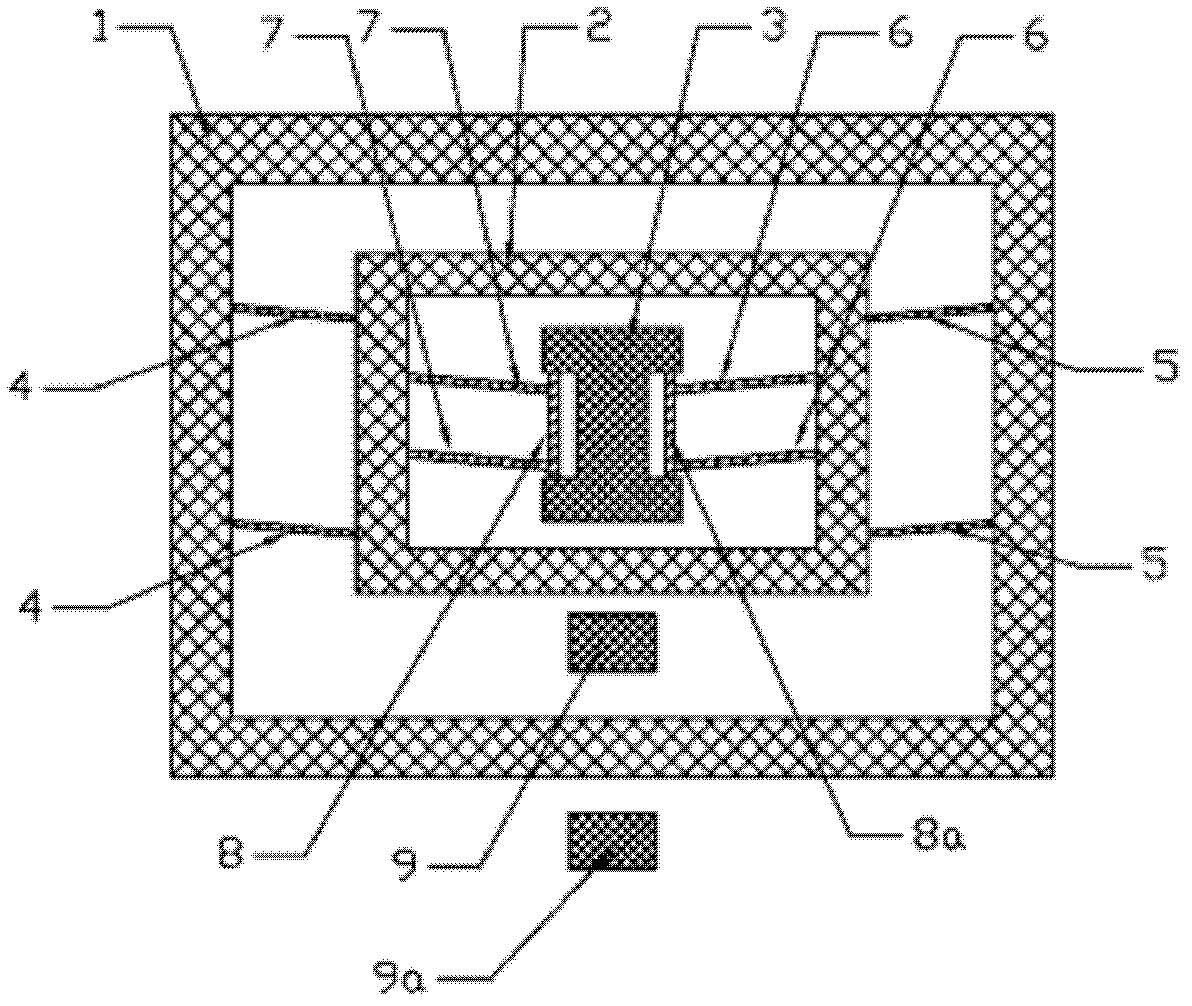
[0026] figure 1 A structural diagram of a dual-threshold tri-stable crash sensor is shown. In the figure, a dual-threshold tri-stable collision sensor includes: an outer mass 1, an inner mass 2, a fixed block 3, a first parallel beam 4, a second parallel beam 5, a third parallel beam 6 and a fourth parallel beam 7. The first contact 9 and the second contact 9a. Both ends of the first side beam 8 and the second side beam 8 a are connected to the fixing block 3 . The third parallel beam 6 and the fourth parallel beam 7 connect the inner mass block 2 to the fixed block 3 to form a support structure; the two ends of the first parallel beam 4 and the second parallel beam 5 are respectively connected to the outer side and the outer side of the inner mass block 2 The inner side of the outer mass 1. The first contact 9 is fixed between the inner mass 2 and the outer mass 1, and the second contact 9a is fixed on the outside of the outer mass.
[0027] When there is no collision, th...
Embodiment 2
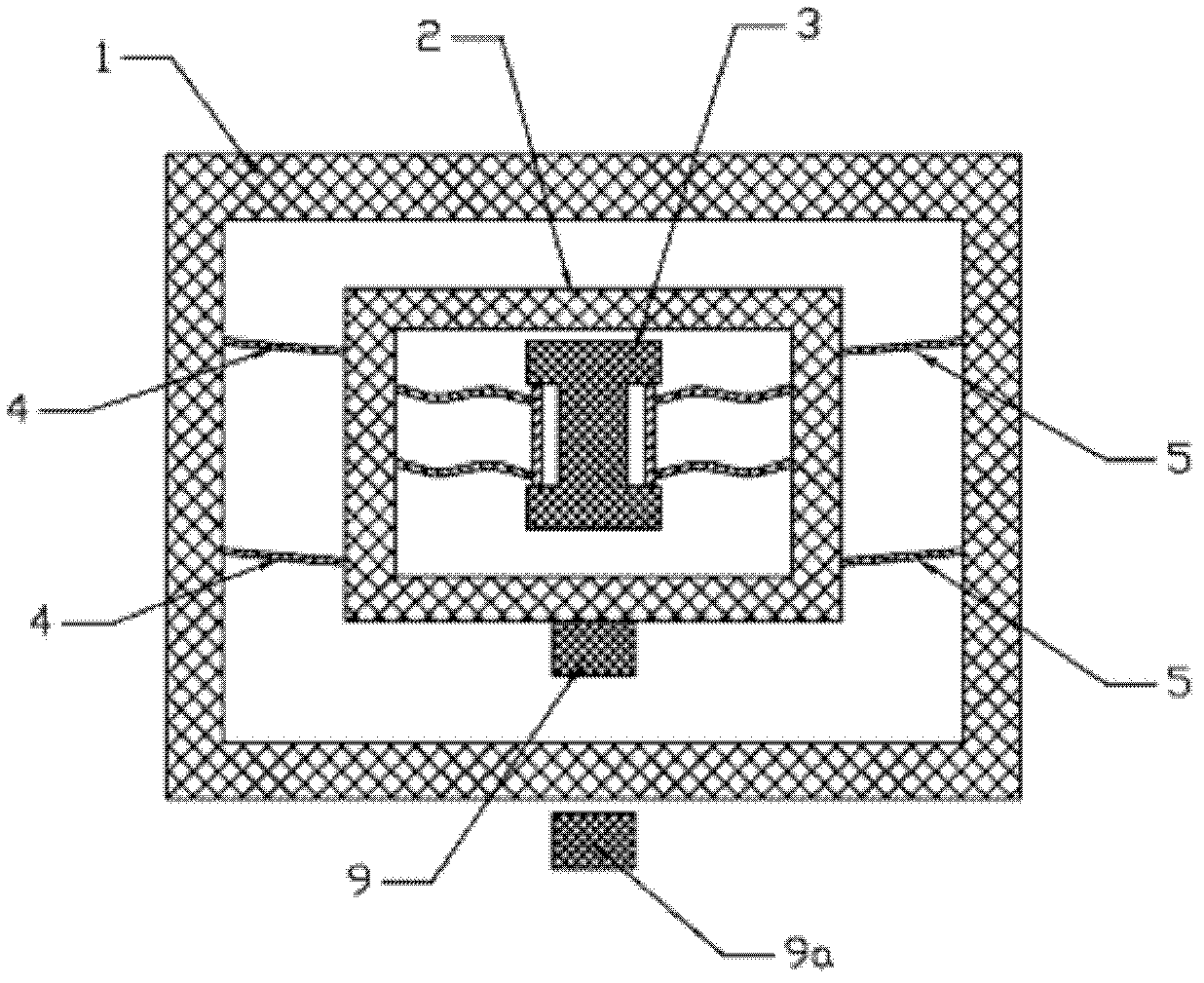
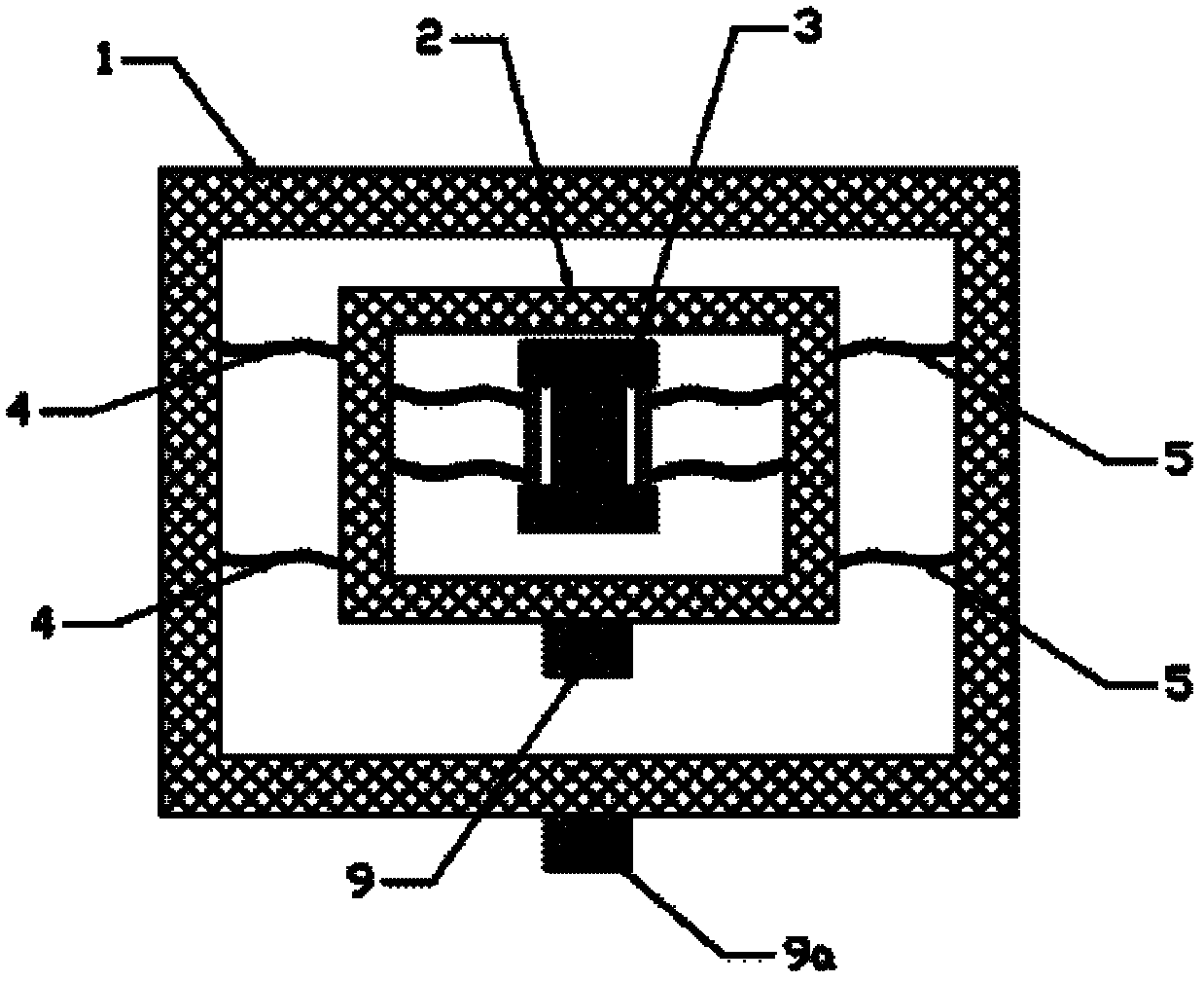
[0032] Figure 4 , 5 , 6 gives another structure diagram of a double-threshold tri-stable collision sensor. In the figure, on the basis of Embodiment 1, the fifth parallel beam 10 and the sixth parallel beam 11 are used to replace the first parallel beam 4 and the second parallel beam 5 in Embodiment 1, the contact 9b replaces the contact 9a, and placed on top of the outer mass. The sum of the inclination angles of the fifth parallel beam and the sixth parallel beam is equal to 180 degrees. The angles of the fifth parallel beam 10 and the sixth parallel beam 11 are equal in size and opposite to the inclination angles of the third parallel beam 6 and the fourth parallel beam 7 . Figure 5 and Figure 6 Two other stable states for this embodiment are given. This type of sensor can sense collision accidents with different thresholds in different directions, that is, the sensing function of external collisions in different directions.
[0033] When the outer collision exceed...
Embodiment 3
[0036] Figure 7 The structure diagram of the third dual-threshold tri-stable crash sensor is given. In the figure, on the basis of Embodiment 1 and Embodiment 2, the third side beam 8b, the fourth side beam 8c, the fifth side beam 8d, the sixth side beam 8e, the seventh side beam 8f and the eighth side beam are used 8j serves as a flexible connection to replace the original rigid connection. The two ends of the third side beam 8b and the fourth side beam 8c are connected to the inner side of the inner mass block 2, and the middle part is connected to one end of the third parallel beam 6 and the fourth parallel beam 7. Both ends of the sixth side beam 8e and the fifth side beam 8d are connected to the outside of the inner mass 2 , and the middle part is connected to one end of the fifth parallel beam 10 and the sixth parallel beam 11 . Both ends of the seventh side beam 8f and the eighth side beam 8j are connected to the inside of the outer mass 1 , and the middle part is con...
PUM
 Abstract
Description
Claims
Application Information
 - R&D
- Intellectual Property
- Life Sciences
- Materials
- Tech Scout
- Unparalleled Data Quality
- Higher Quality Content
- 60% Fewer Hallucinations
Browse by: Latest US Patents, China's latest patents, Technical Efficacy Thesaurus, Application Domain, Technology Topic, Popular Technical Reports.
© 2025 PatSnap. All rights reserved.Legal|Privacy policy|Modern Slavery Act Transparency Statement|Sitemap|About US| Contact US: help@patsnap.com


