Cam mechanism and rotating ring forced resetting device for fingerprint lock

A technology of cam mechanism and reset device, which is applied in the field of anti-theft locks, and can solve the problems of large radial size, narrow space, separation of double clutches, and the reliability of closed locks, which affect the safety of locks.

Active Publication Date: 2017-08-11
重庆桐雨石科技有限公司
View PDF12 Cites 31 Cited by
  • Summary
  • Abstract
  • Description
  • Claims
  • Application Information

AI Technical Summary

Problems solved by technology

If additional relevant components are added on the basis of the two patented technologies to realize the forced reset function of the rotating ring, there are two difficulties involved: one is that there is no space or position for setting the third flange on the driven ring of the cam mechanism, That is to say, it is impossible to complete the forced reset function of the rotating ring by using it with the reset column on the outer rotating ring; the second is that the parts that can be provided with an inclined push surface and matched with the reset lever or the push edge boss only do the unlocking action, not locking Action, so this part cannot be used to realize the forced reset function of the rotating ring
[0007] In addition, in the cam mechanism of the two patent applications "Cam mechanism with fixed lock core and fingerprint lock" and "Cam mechanism of a fingerprint lock", the active plate, touch bead, The driven plate, thrust spring or disc spring are still arranged in the axial direction, occupying more space in the axial direction, forcing the diameter of the bead to be reduced from 8 mm to 6 mm because of the small space
The unfavorable factors of the bead becoming smaller are: the processing accuracy of the parts in contact with the bead is very high, and there are problems in reliability: if the machining error is large, it will either be stuck and cannot idle, or the idling resistance torque is too small, and the lock can be unlocked and locked

Method used


Image

  • Cam mechanism and rotating ring forced resetting device for fingerprint lock
  • Cam mechanism and rotating ring forced resetting device for fingerprint lock
  • Cam mechanism and rotating ring forced resetting device for fingerprint lock

Examples


Embodiment Construction

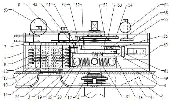
[0056] Combine below Figure 1 to Figure 27 The present invention is further described.

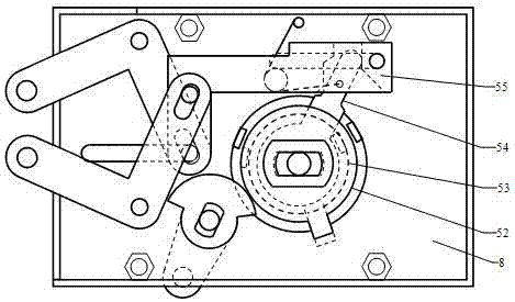
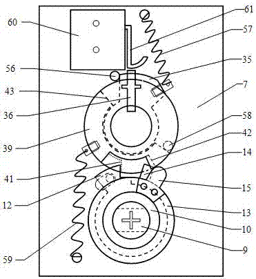
[0057] Such as figure 1 As shown, in the lock body 5 of the anti-theft lock matched with the device of the present invention, the lock cylinder group and the cam mechanism are all installed between the tamper-resistant plate 6 and the back plate 7, and the lock cylinder 9, the cam mechanism and the fingerprint collector 4 ( Can also include the password input window) are all arranged on the same vertical line, that is, the lock core 9 and the key insertion channel 3 are all located directly below the handle shaft of the handle 2. Such as figure 2 As shown, the transmission parts of the lock set matched with the device of the present invention are located between the back plate 7 and the buckle cover 8, and the corresponding lock cylinder 9 and cam mechanism are arranged in a horizontal direction. image 3 It is a schematic diagram of the assembly of the lock cylinder group in the vert...


PUM


Abstract

The invention discloses a cam mechanism and rotating ring forced resetting device for a fingerprint lock and relates to the field of anti-theft locks. According to the cam mechanism and rotating ring forced resetting device for the fingerprint lock, the main improvement is that the specific structure and the assembling mode of an overload protection device of the cam mechanism are changed; a collision bead sliding way, a collision bead spring and the like are radially assembled onto a cam shaft which is amplified locally; meanwhile, a collision bead large in diameter is adopted, on one hand, it is guaranteed that the idle function of the cam mechanism is stable and reliable, and on the other hand, space can be saved; the rotating ring forced resetting device which is simple and easy to implement can be arranged conveniently so that potential dangers can be eliminated; in addition, the resetting device is free of wear in routine operation and low in production cost; and meanwhile, axial dimensions and radial dimensions of main components of a double clutch can be increased so that reliability of the double clutch and safety of the lock can be improved.

Description

technical field [0001] The invention relates to the field of anti-theft locks, in particular to a cam mechanism and a rotating ring forced reset device of a fingerprint lock. Background technique [0002] The invention patent of "Cylinder fixed cross mechanical anti-theft lock" (ZL201410020215.X) in the prior art has special structural and performance advantages: technology cannot be opened, force-opening tools cannot be destroyed, large number of keys, and keys can be used digitally Code representation and preparation, the marbles in the lock cylinder are all steel balls, the key can only be inserted or withdrawn, it does not rotate and is easy to insert and pull out, use the rotating handle to unlock or lock, the handle has an overload protection device to idle, unlock or lock operation Simple and easy and more. Because this product is not only used independently for anti-theft doors, safes, vaults, etc., it can also be used in conjunction with fingerprint recognition sys...

Claims


Application Information

Patent Timeline
IPC IPC(8): E05B15/00E05B47/00E05B49/00
CPCE05B47/0012E05B49/00E05B2047/0018E05B2047/0024E05B2047/0026E05B2047/0037
Inventor 吕雪寒
Owner 重庆桐雨石科技有限公司
Why Eureka
Try Eureka