Adjustable hydraulic gear shaft transmission mechanism

A transmission mechanism and gear shaft technology, applied in engine control, engine components, machine/engine, etc., can solve the problems of increased sealing difficulty, high hydraulic adjustment pressure, and low adjustment accuracy

Active Publication Date: 2017-08-11
NINGBO C S I POWER CO LTD
View PDF7 Cites 0 Cited by
  • Summary
  • Abstract
  • Description
  • Claims
  • Application Information

AI Technical Summary

Problems solved by technology

[0003] 1. The hydraulic adjustment mechanism is based on the design principle, and the adjustment torque is too small due to insufficient strength;
[0004] 2. The hydraulic adjustment stroke is small, resulting in low adjustment accuracy and poor self-stabilization ability;
[0005] 3. High hydraulic adjustment pressure, resulting in increased sealing difficulty
[0006] In addition to the above reasons, part of the hydraulic adjustment scheme is installed on the camshaft, resulting in the disturbance of the transmission mechanism directly affecting the operation of the camshaft during the adjustment process.

Method used


Image

  • Adjustable hydraulic gear shaft transmission mechanism
  • Adjustable hydraulic gear shaft transmission mechanism
  • Adjustable hydraulic gear shaft transmission mechanism

Examples


Embodiment Construction

[0025] The present invention will be further described in detail below in conjunction with the accompanying drawings and embodiments.

[0026] Such as Figure 1 to Figure 4 The example shown,

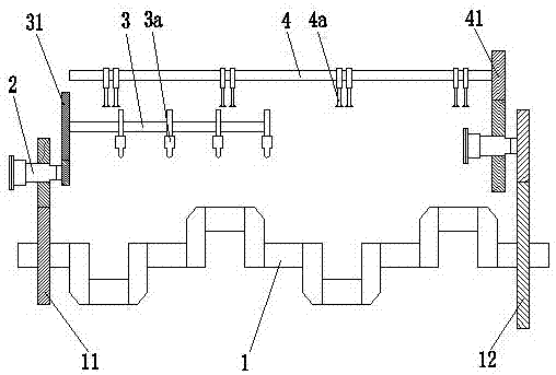
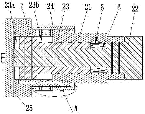
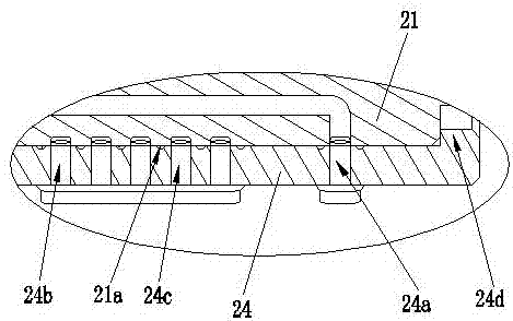
[0027] Description of icon numbers: crankshaft 1, free end gear 11, flywheel end gear 12, adjustment mechanism 2, outer shaft 21, high pressure sealing ring 21a, mandrel 22, adjustment shaft 23, left oil chamber 23a, right oil chamber 23b, oil delivery Valve 24, left injection hole 24a, right injection hole 24b, feedback hole 24c, rib 24d, cover plate 25, high pressure oil pump shaft 3, high pressure oil pump 3a, high pressure oil pump shaft gear 31, camshaft 4, air valve 4a, camshaft Gear 41, spiral tooth groove 5, spline tooth groove 6, sealing ring 7, pressure sensor 81, control system 82, oil return valve 83, hydraulic electric control valve 84, main hydraulic valve 85, hydraulic oil pump 86.

[0028] Such as Figure 1 to Figure 4 as shown,

[0029] An adjustable hydraulic gear ...


PUM


Abstract

The invention discloses an adjustable hydraulic gear shaft transmission mechanism. A free end gear of a crankshaft is in transmission connection with a high-pressure oil pump shaft gear at the end part of a high-pressure oil pump shaft by an adjusting mechanism; a flywheel end gear is in transmission connection with a camshaft gear at the end part of a camshaft by an adjusting mechanism; the adjusting mechanism comprises an outer shaft, a mandrel, an adjusting structure with a T-shaped structure, an oil transmission valve and a cover plate; the adjusting shaft is sleeved on the mandrel; the outer shaft is assembled out of the adjusting shaft; a left oil cavity is formed between the left end of the adjusting shaft and the cover plate; a right oil cavity is formed between the adjusting shaft and the outer shaft; the oil transmission cavity is assembled out of the outer shaft; a left injection hole on the oil transmission valve communicates with the left oil cavity; a right injection hole on the oil transmission valve communicates with the right oil cavity; the adjusting shaft and the outer shaft are engaged by a spiral tooth groove; and the adjusting shaft and the mandrel are matched by a spline tooth groove. The adjustable hydraulic gear shaft transmission mechanism has the advantages of: reasonable structure, capability of increasing the adjusting torque, improving the adjusting precision and reducing the adjusting pressure, and change of the intake / exhaust valve timing and the oil injection timing.

Description

technical field [0001] The invention relates to the technical field of hydraulic transmission, in particular to an adjustable hydraulic gear shaft transmission mechanism, in particular to a gear shaft transmission mechanism for realizing variable fuel injection timing and variable valve timing of an engine. Background technique [0002] With the rapid development of internal combustion engine technology in the country, in the field of internal combustion engines for vehicles, in order to improve the fuel consumption and exhaust emissions of internal combustion engines, many technologies that adjust variable valve timing through hydraulic pressure have emerged. However, since this type of technology is mainly aimed at the field of internal combustion engines for vehicles, these technologies cannot be applied to the field of high-power marine medium-speed diesel engines at present. The main reasons mainly include: [0003] 1. The hydraulic adjustment mechanism is based on the...

Claims


Application Information

Patent Timeline
IPC IPC(8): F01L1/344F02D1/16
CPCF01L1/344F02D1/16F01L2800/00
Inventor 周辉王雷郑翱昱刘开敏吴杰
Owner NINGBO C S I POWER CO LTD
Why Eureka
Try Eureka