
Treatment casing with adjustable grooving width of centrifugal air compressor

A centrifugal compressor and casing processing technology, which is applied in the direction of machines/engines, mechanical equipment, liquid fuel engines, etc., can solve the problems of not being able to meet the different requirements of the casing, and the effect of expanding stability, so as to improve the stable working range and improve The effect of pressure ratio and adiabatic efficiency

Inactive Publication Date: 2017-08-11
HEFEI UNIV OF TECH
View PDF5 Cites 9 Cited by
  • Summary
  • Abstract
  • Description
  • Claims
  • Application Information

AI Technical Summary

Problems solved by technology

[0004] At present, it is considered that treating the casing is an effective method to expand the stable working range of the centrifugal compressor. Studies have shown that the position of the suction ring groove relative to the leading edge of the mainstream blade of the centrifugal compressor directly determines the return pressure difference and return flow rate, and has the greatest impact on the stability expansion effect. , but because the casing generally adopts a fixed and non-adjustable structure, the compressor cannot meet the different requirements for casing processing under different working conditions

Method used


Image

  • Treatment casing with adjustable grooving width of centrifugal air compressor
  • Treatment casing with adjustable grooving width of centrifugal air compressor
  • Treatment casing with adjustable grooving width of centrifugal air compressor

Examples


Embodiment Construction

[0020] The structure, principle and working process of the present invention will be described in detail below in conjunction with the drawings and embodiments.

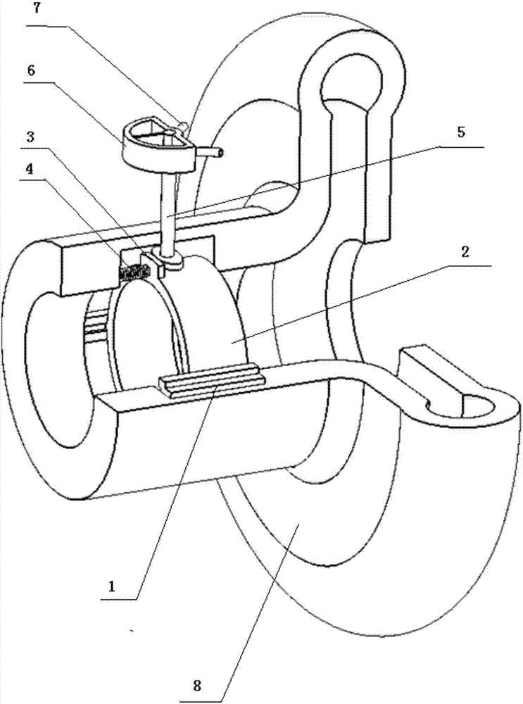
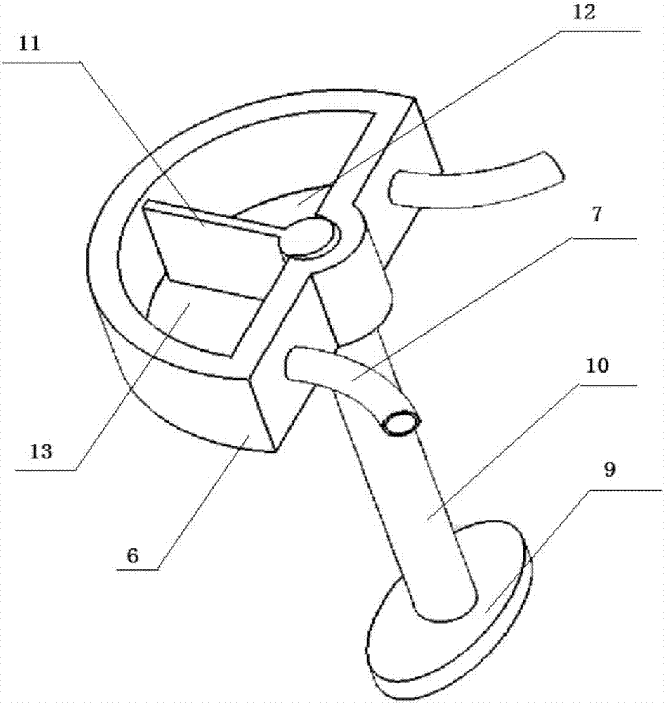
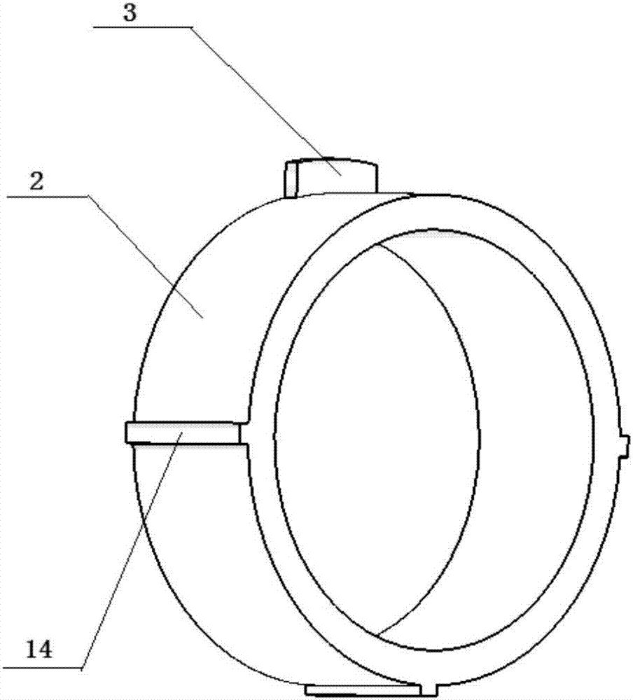
[0021] see figure 1 , figure 2 , image 3 with Figure 4 The centrifugal compressor treatment casing with adjustable slot width provided by the present invention contains a suction ring groove 15, a return ring groove 117 and a guide ring groove 16 arranged in the volute, the suction ring groove, the return ring groove The groove and the guide ring groove form a self-circulating casing channel; the centrifugal compressor processing casing also includes an adjusting device with adjustable slot width, which includes a hollow cylinder 2, a cam structure, a coil spring 4 and two guides. Trachea 7; the hollow cylinder 2 is arranged in the guide ring groove 16, and is connected with the guide ring groove through a moving pair, and the moving pair preferably adopts a slide block-rail mechanism, and the slide block 14 is...


PUM


Abstract

The invention discloses a treatment casing with an adjustable grooving width of a centrifugal air compressor. The casing comprises a self-circulation casing channel formed in a volute, and an adjustment device with the adjustable grooving width, wherein the adjustment device comprises a hollow cylinder, a cam structure and a spiral spring; the hollow cylinder is arranged in a flow guide ring groove and moves along the flow guide ring groove; and the cam structure comprises a cam, a cam shaft and a sealing hollow structure arranged on the upper part of the cam shaft, the interior of the sealing hollow structure is divided into two chambers, each chamber is connected with an air guide pipe, and the other ends of the air guide pipes are connected to the different positions in the circumferential direction of the volute. The cam shaft is pushed to rotate through the pressure difference of the two chambers to drive the hollow cylinder to move, so that a casing design that the width of a suction ring groove is adjusted with the working condition of the air compressor. According to the technical scheme of the invention, compared with a self-circulation treatment casing with a fixed-width suction ring groove, the width of the suction ring groove can be adjusted, so that the stable working range of the centrifugal air compressor can be greatly expanded, and the pressure ratio and the adiabatic efficiency of a part of working conditions are increased.

Description

technical field [0001] The invention relates to the technical field of impeller machinery, in particular to a centrifugal compressor processing casing, which can be widely used in the fields of vehicle pressurized centrifugal compressors, industrial centrifugal compressors, aviation centrifugal compressors and the like. Background technique [0002] The impeller compressor is divided into two basic types: axial flow compressor and centrifugal compressor. Compared with the multi-stage axial flow compressor, the centrifugal compressor has the advantages of simple structure, light weight, small volume, etc., and can maintain high efficiency in a wide operating range, so it is used in car and ship turbochargers, It is widely used in some industrial compressors and aviation compressors and other facilities. [0003] As a turbomachinery, the centrifugal compressor is limited by blockage and surge in its stable working range. When the flow rate decreases to a certain level, large...

Claims


Application Information

Patent Timeline
IPC IPC(8): F04D29/46F04D29/42F04D27/02
CPCF04D27/0246F04D29/4206F04D29/464
Inventor 汪陈芳张睿栋张扬军诸葛伟林程晓章
Owner HEFEI UNIV OF TECH
Learn More