Refrigerating cycle system

A refrigeration cycle and refrigerant circuit technology, which is applied in the direction of refrigerators, refrigeration components, refrigeration and liquefaction, etc., can solve the problems of cost, man-hours, inability to effectively adjust, and unclear criticality of refrigerant quantity, etc.

Inactive Publication Date: 2017-08-11
HITACHI JOHNSON CONTROLS AIR CONDITIONING INC
View PDF6 Cites 2 Cited by
  • Summary
  • Abstract
  • Description
  • Claims
  • Application Information

AI Technical Summary

Problems solved by technology

[0015] However, in the technique of Patent Document 1, since it is necessary to deliberately provide an air adsorption mechanism in the refrigerant circuit, the cost and man-hours are correspondingly required.
In addition, since the quantitative correlation between the amount of air (oxygen) in the refrigerant and the performance degradation of the refrigeration cycle device is unclear, the allowable air (oxygen) in the refrigerant is unclear from the viewpoint of the performance of the refrigeration cycle device. The amount of oxygen) is critical, so the amount of air (oxygen) in the refrigerant cannot be effectively adjusted

Method used


Image

  • Refrigerating cycle system
  • Refrigerating cycle system
  • Refrigerating cycle system

Examples


Embodiment Construction

[0052] Hereinafter, modes for implementing the present invention (hereinafter referred to as "embodiments") will be described in detail with reference to appropriate drawings. In addition, in each figure, the same code|symbol is attached|subjected to the same structure, and repeated description is abbreviate|omitted suitably.

[0053] (Structure of refrigeration cycle device)

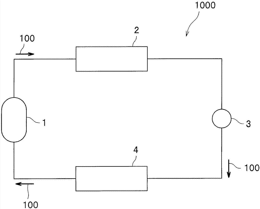
[0054] First, refer to figure 1 The configuration of the refrigeration cycle apparatus 1000 of this embodiment will be described. In the refrigeration cycle apparatus 1000 , a compressor 1 , a condenser 2 (heat exchanger), an expansion mechanism 3 , and an evaporator 4 (heat exchanger) are connected by piping to form a refrigerant circuit in which a refrigerant 100 circulates. As the refrigerant 100, difluoromethane (HFC32) is used.

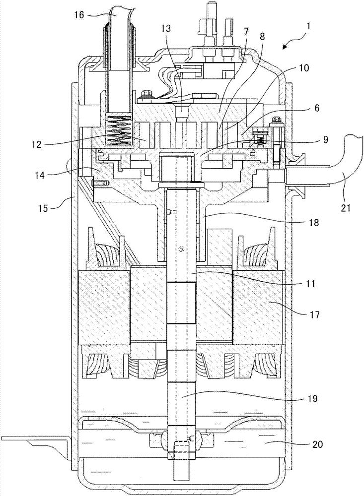
[0055] The compressor 1 is provided with a refrigerant compression part having a sliding part, and difluoromethane (HFC32) and refrigerating machine oil are sealed as a...


PUM


Abstract

In order to solve a problem of adjusting effectively an air amount in the refrigerant, when difluoromethane (HFC32) is used for the refrigerant in the refrigerating cycle system, the present invention provides a refrigerating cycle system 1000 that is provided with a refrigerant circuit circulating a refrigerant 100 by connecting using pipes: a compressor 1 in which difluoromethane (HFC32) 10 as the refrigerant 100 and refrigerator oil including phenolic DBPC (2,6-di-t-b-t-l-craess aonl) a ntioxidant are sealed; a condenser 2; an expansion unit 3; and an evaporator 4, wherein an air amount (pressure) contained in the refrigerant 100 is 20 kPa or less.

Description

[0001] This application is a divisional application of the national phase application number 201410379967.5, the application date is August 4, 2014, and the invention title is "refrigeration cycle device and air conditioning device". technical field [0002] The present invention relates to a refrigeration cycle (heat pump cycle) device used in an air conditioner (air conditioner, etc.), a water heater, and the like. Background technique [0003] Generally, compressors, condensers (heat exchangers), expansion valves, and evaporators (heat exchangers) are The pipes are connected to form a refrigerant circuit that circulates the charged refrigerant. Then, the refrigerant compressed by the compressor becomes high-temperature and high-pressure gas refrigerant, and is sent to the condenser. The refrigerant that has flowed into the condenser is liquefied by releasing heat through heat exchange with a heat exchange object (air, etc.). The liquefied refrigerant is decompressed by ...

Claims


Application Information

Patent Timeline
Patent Type & Authority Applications(China)
IPC IPC(8): F25B1/04F25B43/04F25B41/30F25B41/31F25B41/37
CPCF25B1/04F25B29/003F25B43/043F25B41/30
Inventor 秋山智仁田所哲也村上晃启实川仁美渕野大我井关崇
Owner HITACHI JOHNSON CONTROLS AIR CONDITIONING INC
Why Eureka
Try Eureka