Voltage ripple detection circuit

A detection circuit and filter circuit technology, applied in the direction of measuring current/voltage, measuring device, measuring electrical variables, etc., can solve problems such as changes, failure to work normally, and equipment reliability decline

Pending Publication Date: 2017-08-11
GREE ELECTRIC APPLIANCES INC
View PDF4 Cites 5 Cited by
  • Summary
  • Abstract
  • Description
  • Claims
  • Application Information

AI Technical Summary

Problems solved by technology

[0003] The technical problem to be solved by the present invention is that at present, various electrical equipment only limit the ripple in the early stage of design, and the internal ripple may change when the equipment is working later, resulting in a decrease in reliability of the equipment or even failure to work normally.

Method used


Image

  • Voltage ripple detection circuit
  • Voltage ripple detection circuit
  • Voltage ripple detection circuit

Examples


Embodiment Construction

[0023] In order to make the purpose, technical solutions and advantages of the embodiments of the present invention clearer, the technical solutions in the embodiments of the present invention will be clearly and completely described below in conjunction with the drawings in the embodiments of the present invention. Obviously, the described embodiments It is a part of embodiments of the present invention, but not all embodiments. Based on the embodiments of the present invention, all other embodiments obtained by those skilled in the art without creative efforts fall within the protection scope of the present invention.

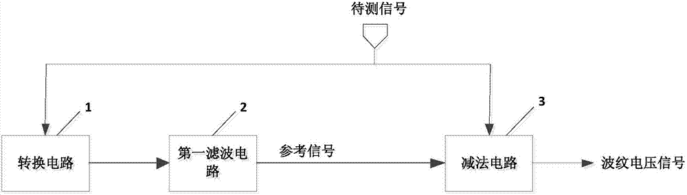
[0024] figure 1 is a schematic diagram of a voltage ripple detection circuit provided by an embodiment of the present invention, such as figure 1 As shown, the circuit includes:

[0025] The conversion circuit 1 is used to convert the signal to be tested into a pulse signal; the signal to be tested is, for example, the output signal of a DC stabilized power...


PUM


Abstract

The invention discloses a voltage ripple detection circuit, and the circuit comprises a conversion circuit which is used for converting a to-be-detected signal into a pulse signal; a first filtering circuit which is used for filtering the pulse signal to generate a reference signal; and a subtraction circuit which is used for carrying out the subtraction of the to-be-detected signal and the reference signal so as to obtain a ripple voltage signal. Therefore, the circuit achieves the detection of voltage ripples when equipment is in operation.

Description

technical field [0001] The invention relates to the technical field of electronic measurement, in particular to a voltage ripple detection circuit. Background technique [0002] At present, all kinds of electrical equipment have more and more strict requirements on the power supply ripple, but the current equipment basically only limits the ripple in the early stage of design. In this case, for some devices with high requirements on ripple, with the prolongation of service time, or the change of electrolytic capacitor capacitance under low temperature conditions, the internal ripple of the circuit will increase, resulting in a decrease in the reliability of the device. Poor, even equipment not working properly. Contents of the invention [0003] The technical problem to be solved by the present invention is that current various electrical equipment only limits the ripple in the early stage of design, and the internal ripple may change when the equipment is in operation la...

Claims


Application Information

Patent Timeline
IPC IPC(8): G01R19/04G01R19/00
CPCG01R19/0053G01R19/04
Inventor 杨坚宋爱程海松张大龙戴彪
Owner GREE ELECTRIC APPLIANCES INC
Why Eureka
Try Eureka