Hospital bed information monitoring system

An information monitoring and hospital bed technology, applied in the medical field, can solve the problems of monitoring, heavy workload, and difficulty in ensuring the collection of monitoring data, and achieve the effect of being convenient to use and avoiding obstacles.

Inactive Publication Date: 2019-09-17
狄浩
View PDF10 Cites 2 Cited by
  • Summary
  • Abstract
  • Description
  • Claims
  • Application Information

AI Technical Summary

Problems solved by technology

[0004] The purpose of the present invention is to provide a kind of sick bed information monitoring system, to solve the existing sick bed information monitoring system proposed in the above-mentioned background technology mainly depends on the observation of doctors, nurses patrolling or patient caregivers, and the processing mode of caregivers is usually through Calling and ringing the bell to call the doctor, so the patient care work is not only cumbersome and the workload is heavy, but also it is difficult to ensure real-time and uninterrupted collection of monitoring data. The current monitoring system in application or research is often limited to local functions, such as hospital beds Call and infusion monitoring systems also have researches based on networking methods, such as intelligent medical monitoring systems based on the Internet of Things, etc., but there is no problem with networked, intelligent, and real-time systems that specifically monitor, control, and manage the treatment process of inpatients

Method used


Image

  • Hospital bed information monitoring system
  • Hospital bed information monitoring system
  • Hospital bed information monitoring system

Examples


Embodiment Construction

[0036] The following will clearly and completely describe the technical solutions in the embodiments of the present invention with reference to the accompanying drawings in the embodiments of the present invention. Obviously, the described embodiments are only some, not all, embodiments of the present invention.

[0037] In the description of the present invention, unless otherwise stated, the meaning of "plurality" is two or more; the terms "upper", "lower", "left", "right", "inner", "outer" , "front end", "rear end", "head", "tail", etc. indicate the orientation or positional relationship based on the orientation or positional relationship shown in the drawings, and are only for the convenience of describing the present invention and simplifying the description, rather than Nothing indicating or implying that a referenced device or element must have a particular orientation, be constructed, and operate in a particular orientation should therefore not be construed as limiting ...


PUM


Abstract

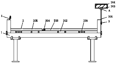
The invention relates to a hospital bed information monitoring system. The hospital bed information monitoring system comprises a hospital bed and an intelligent bracelet device, wherein a hospital bed recording device is arranged at the upper end of the hospital bed; a monitoring intelligent terminal device is arranged at the upper end of one side of the hospital bed; the intelligent bracelet device is embedded in the upper end of the other side of the hospital bed; an infusion managing device is connected to the front surface of the hospital bed; the inner part of the hospital bed recording device comprises a vibration sensor; a pressure sensor is mounted on one side of the vibration sensor; a first bed board is embedded in the upper end of the pressure sensor; a rotating shaft is connected to one side of the first bed board; and a second bed board is mounted on one side of the rotating shaft. The hospital bed monitoring system disclosed by the invention has the beneficial effects that the vibration sensor and the pressure sensor are separately arranged at the lower end of the first bed board and the lower end of the second bed board, so that the situations of the body weight, overturning, rising and the like of a patient can be detected, and detection can be performed on the patient; and when the second bed board is overturned, the hospital bed can also perform detection on the patient.

Description

technical field [0001] The invention relates to the field of medical technology, in particular to a hospital bed information monitoring system. Background technique [0002] Hospitalization is an important means for doctors to conduct round-the-clock diagnosis and treatment of critically ill patients. During this period, the patient spends most of his time on the hospital bed, and doctors need to monitor his physiological data and diagnosis and treatment process in real time. [0003] The existing bed information monitoring system mainly relies on the inspection of doctors and nurses or the observation of patient caregivers. The caregivers often call the doctor by shouting and ringing the bell. Therefore, the patient care work is not only cumbersome, but also difficult Ensure real-time and uninterrupted collection of monitoring data. The monitoring systems in current applications or research are often limited to local functions, such as hospital bed call and infusion monitor...

Claims


Application Information

Patent Timeline
Patent Type & Authority Applications(China)
IPC IPC(8): A61G7/015A61G7/05A61M5/168A61B5/11A61B5/00A61B90/98G01G19/50G01S19/14
CPCA61B5/1112A61B5/1114A61B5/681A61B5/6891A61B90/98A61G7/015A61G7/05A61M5/16845G01G19/50G01S19/14
Inventor 狄浩
Owner 狄浩
Why Eureka
Try Eureka