Wiring structure for low voltage signal double winding transformer partial discharge test

A dual-winding transformer, partial discharge technology, applied in the parts, instruments, measuring electrical variables and other directions of electrical measuring instruments, can solve the problem of low test voltage, affecting the safe and reliable operation of ultra-high voltage transformers of transformers, and overloading of transformer pressurized sides. Equipment capacity and other issues to achieve the effect of reducing requirements and increasing test costs

Pending Publication Date: 2017-08-11
ZHEJIANG THERMAL POWER CONSTR
View PDF0 Cites 3 Cited by
  • Summary
  • Abstract
  • Description
  • Claims
  • Application Information

AI Technical Summary

Problems solved by technology

During the partial discharge test, since the capacitive current of the high-voltage winding is coupled to the pressurized side through the transformation ratio, and the test voltage of the pressurized side is generally relatively low due to the reason of the wiring group, this makes the reactive current of the transformer pressurized side Too large exceeds the capacity of the test equipment, and the conventional equipment configuration of the debugging unit is difficult to meet the test requirements
[0003] During the long-term operation of the transformer, some weak parts of its internal insulation will undergo partial discharge under the action of high field strength, which will lead to a decrease in insulation performance. Under the long-term action of severe partial discharge, it will even cause the breakdown of the transformer. Therefore, Affect the safe and reliable operation of transformers, especially ultra-high voltage transformers, under long-term working voltage

Method used


Image

  • Wiring structure for low voltage signal double winding transformer partial discharge test

Examples


Embodiment Construction

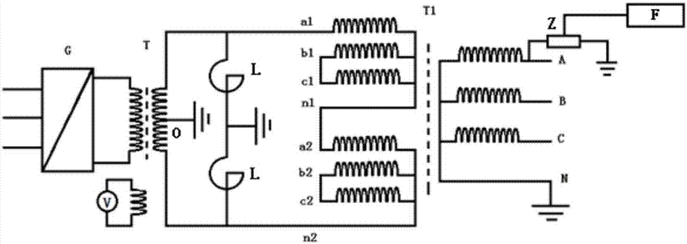
[0019] Referring to the accompanying drawings, a wiring structure for a partial discharge test of a double-winding transformer on the low-voltage side, including a partial discharge-free variable frequency power supply G, a non-partial discharge excitation transformer T, a tested low-voltage side double-winding transformer T1 and a partial discharge detector F;

[0020] The non-partial discharge variable frequency power supply G is connected to the input end of the non-partition discharge excitation transformer T, the output of the non-partition discharge excitation transformer T adopts a symmetrical output, and the output end of the non-partition discharge excitation transformer T has a first terminal and the second terminal, and the middle O of the first terminal and the second terminal is grounded; the first terminal and the second terminal are each connected to a compensation reactor combination, and the tail end of the compensation reactor combination grounding; the output...


PUM


Abstract

The invention discloses a wiring structure for a low voltage signal double winding transformer partial discharge test. The middle of the first terminal and the second terminal of a partial discharge-free excitation transformer is grounded. The first terminal and the second terminal are connected with a compensation reactor combination respectively. One terminal of the phase winding of a first low voltage winding is connected with the first terminal of the partial discharge-free excitation transformer, and the other two terminals of the phase winding of the first low voltage winding are interconnected. The neutral point terminal of the first low voltage winding is connected with one terminal of the phase winding of a second low voltage winding. The two terminals of the phase winding of the second low voltage winding are interconnected. The neutral point terminal of the second low voltage winding is connected with the second terminal of the partial discharge-free excitation transformer. The bushing end screen terminal of the tested phase at the high voltage side of the tested low voltage side double winding transformer is grounded via a detection impeder, and the detection impeder is connected with the partial discharge detector.

Description

technical field [0001] The invention relates to a wiring structure for a partial discharge test of a low-voltage side double-winding transformer. Background technique [0002] In recent years, in order to save investment costs, large power plants generally design only one start-up backup transformer. This type of transformer has a special structure and has the characteristics of large capacity, large transformation ratio, and double windings on the low-voltage side. During the partial discharge test, since the capacitive current of the high-voltage winding is coupled to the pressurized side through the transformation ratio, and the test voltage of the pressurized side is generally low due to the reason of the wiring group, this makes the reactive current of the transformer pressurized side It is too large to exceed the capacity of the test equipment, and the conventional equipment configuration of the debugging unit is difficult to meet the test requirements. [0003] Duri...

Claims


Application Information

Patent Timeline
IPC IPC(8): G01R31/12G01R1/04
CPCG01R1/0416G01R31/12
Inventor 张马林蒋根华王慧军于世超丘建宇邹光毅吕坚黄骏
Owner ZHEJIANG THERMAL POWER CONSTR
Why Eureka
Try Eureka