Floatable electrical plug support assembly

A floating bracket and electric plug technology, which is applied in the installation of connecting parts and the device for connecting/disconnecting connecting parts, etc., can solve problems such as reducing the service life of electric plugs, and achieve the effect of improving service life and avoiding damage.

Active Publication Date: 2017-08-11
NINGBO HAITIAN PRECISION MASCH CO LTD
View PDF6 Cites 0 Cited by
  • Summary
  • Abstract
  • Description
  • Claims
  • Application Information

AI Technical Summary

Problems solved by technology

That is to say, every time the C-axis of the right-angle head rotates once, the sub-plug and the female plug have one more plugging action, and the plugging and pulling of the electric plug has a life. Therefore, the frequent C-axis indexing action of the right-angle head reduces the The service life of the electric plug

Method used


Image

  • Floatable electrical plug support assembly
  • Floatable electrical plug support assembly
  • Floatable electrical plug support assembly

Examples


Embodiment 1

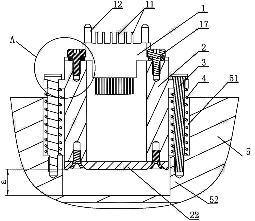
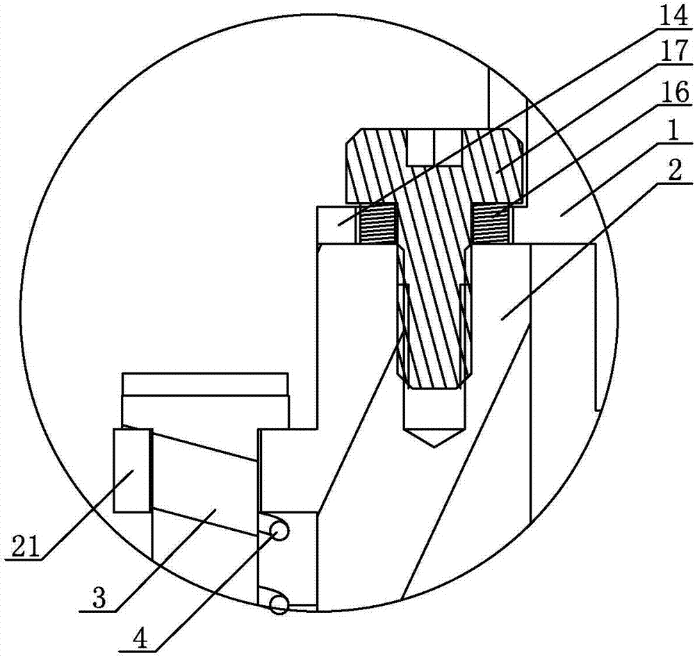
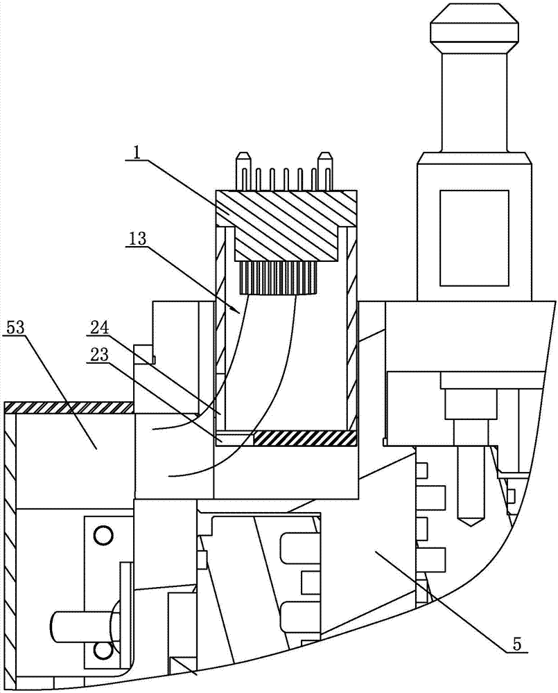
[0027]The floating electrical plug bracket assembly of Embodiment 1, as shown in the figure, the electrical plug includes a suitable sub-plug 1 and a female plug (not shown in the figure), and the sub-plug 1 is provided with several pins 11 and Three guide pins 12, the female plug is provided with several sockets (not shown in the figure) and three pin holes (not shown in the figure) that are compatible with several pins 11 and three guide pins 12, the The bracket assembly includes a floating bracket 2, four guide screws 3 and four springs 4, the floating bracket 2 is floatingly installed on the first machine tool component 5, and the first machine tool component 5 is provided with a concave cavity 51, and the bottom of the floating bracket 2 is arranged on In the concave cavity 51; four guide screws 3 are arranged at intervals along the circumferential direction of the floating support 2, each guide screw 3 passes through the floating support 2 and is threadedly connected with...

Embodiment 2

[0030] The floating electrical plug bracket assembly of Embodiment 2, as shown in the figure, the electrical plug includes a suitable sub-plug 1 and a female plug (not shown in the figure), and the sub-plug 1 is provided with several pins 11 and Three guide pins 12, the female plug is provided with several sockets (not shown in the figure) and three pin holes (not shown in the figure) that are compatible with several pins 11 and three guide pins 12, the The bracket assembly includes a floating bracket 2, four guide screws 3 and four springs 4, the floating bracket 2 is floatingly installed on the first machine tool component 5, and the first machine tool component 5 is provided with a concave cavity 51, and the bottom of the floating bracket 2 is arranged on In the concave cavity 51; four guide screws 3 are arranged at intervals along the circumferential direction of the floating support 2, each guide screw 3 passes through the floating support 2 and is threadedly connected wit...


PUM


Abstract

The invention discloses a floatable electrical plug support assembly. The floatable electrical plug support assembly comprises a floating support, a plurality of guide screws and a plurality of springs, wherein the floating support is arranged on a first machine tool part in a floating way, a concave cavity is formed in the first machine tool part, a lower part of the floating support is arranged in the concave cavity, the plurality of guide screws are arranged at intervals along a circumferential direction of the floating support, each guide screw passes through the floating support and is in threaded connection with the first machine tool part, each spring sleeves each guide screw, a son plug is arranged at an upper end of the floating support, a parent plug is arranged at a lower end of a second machine tool part, the first machine tool part is arranged opposite to the second machine tool part, and the second machine tool part can move upwards and downwards relative to the first machine tool part. By the support assembly, the son plug and the parent plug can be maintained in an abutting state when the second machine tool part downwards move to the maximum range, an electrical plug is prevented from being damaged due to frequent plug-in and plug-out of the son plug and the parent plug, so that the service lifetime of the electrical plug is prolonged.

Description

technical field [0001] The invention relates to a numerical control machine tool accessory, in particular to a floating electric plug bracket assembly. Background technique [0002] When the CNC machine tool is connected to the multi-functional accessory head, it is necessary to transmit several electrical signals on the accessory head to the machine tool ram through the Odu plug or aviation plug, so that the CNC system of the machine tool can recognize the current state of the accessory head, so as to control the accessory head to execute the next step. an instruction. [0003] The electrical plug includes a sub-plug and a female plug. During use, the signal transmission is made on and off by plugging and unplugging the sub-plug and the female plug. However, since the position accuracy required by this type of electric plug is too high, and the butt joint between the sub-plug and the female plug is a rigid connection, when the machine tool grabs the accessory head, it is e...

Claims


Application Information

Patent Timeline
Patent Type & Authority Applications(China)
IPC IPC(8): H01R13/73H01R13/62
CPCH01R13/62H01R13/73Y02T10/70
Inventor 赵岩盛孝勇黄文东
Owner NINGBO HAITIAN PRECISION MASCH CO LTD
Why Eureka
Try Eureka