Clamping device for machining

A clamping device and machining technology, used in positioning devices, metal processing equipment, metal processing mechanical parts, etc., can solve the problems of wasting time, increase processing costs, etc., and achieve convenient use, increase time waste, and improve efficiency. Effect

Active Publication Date: 2017-08-15
宁夏飞天科技有限公司
View PDF6 Cites 23 Cited by
  • Summary
  • Abstract
  • Description
  • Claims
  • Application Information

AI Technical Summary

Problems solved by technology

[0003] The purpose of the present invention is to solve the problem existing in the prior art that when processing workpieces of different sizes, it is necessary to replace different types of pressing plates. During the process of disassembling and assembling the pressing plates, not only wastes more time, but also increases Due to the disadvantages of processing costs, a clamping device for machining is proposed

Method used


Image

  • Clamping device for machining
  • Clamping device for machining
  • Clamping device for machining

Examples


Embodiment Construction

[0015] The following will clearly and completely describe the technical solutions in the embodiments of the present invention with reference to the accompanying drawings in the embodiments of the present invention. Obviously, the described embodiments are only some, not all, embodiments of the present invention.

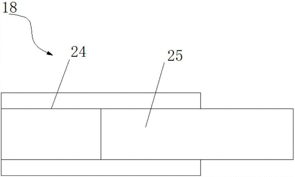
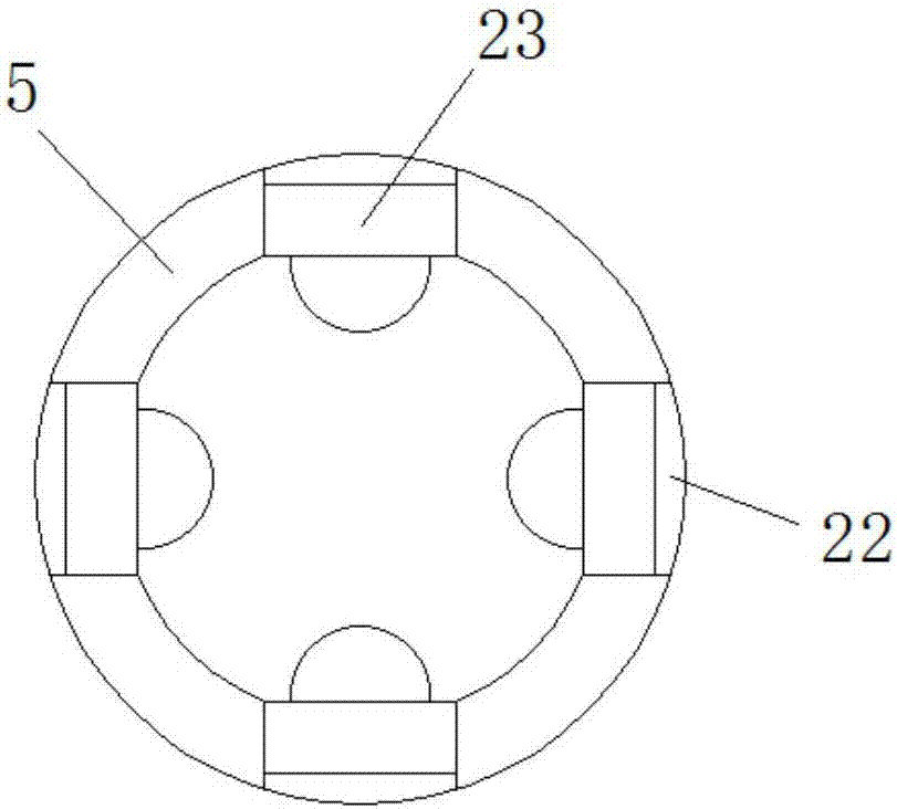
[0016] refer to Figure 1-3 , a clamping device for mechanical processing, including a base 19, a fixed plate 15 is arranged above the base 19, and the fixed plate 15 and the base 19 are connected by two telescopic devices, and a second telescopic device is respectively provided between the two telescopic devices. Two slide bars 6 and the first slide bar 21, telescopic device comprises the second metal pipe fitting 16, and the second metal pipe fitting 16 is connected with fixed plate 15, and the bottom opening of the second metal pipe fitting 16 is plugged with support rod 17, and the support rod 17 is connected to the base 19 at one end away from the second metal p...


PUM


Abstract

The invention relates to the technical field of machining, in particular to a clamping device for machining. The clamping device comprises a base; a fixing plate is arranged above the base; the fixing plate and the base are connected through two telescopic devices; a second sliding rod and a first sliding rod are arranged between the two telescopic devices; a first metal pipe fitting is arranged at the top of the fixing plate in a penetrating mode; a threaded pipe is arranged at the top end of the first metal pipe fitting; internal threads are connected with a screw; a mounting plate is arranged at the top end of the screw; the bottom end of the screw penetrates through the first metal pipe fitting and extends to the position below the fixing plate; the bottom end of the screw is connected with an annular part in a sleeved mode; and limiting blocks are arranged on and under the annular part. The clamping device is simple in structure and convenient to use, a workpiece can be clamped in an adjustment mode according to the size of the workpiece, meanwhile, the waste of time can be greatly reduced, and therefore the working efficiency of machining can be improved.

Description

technical field [0001] The invention relates to the technical field of machining, in particular to a clamping device for machining. Background technique [0002] Before machining, it is necessary to fix the processed workpiece. When processing workpieces of different sizes, it is necessary to replace different types of pressure plates. In the process of disassembling and assembling the pressure plates, it not only wastes more time, but also Increased processing costs. Contents of the invention [0003] The purpose of the present invention is to solve the problem existing in the prior art that when processing workpieces of different sizes, it is necessary to replace different types of pressing plates. During the process of disassembling and assembling the pressing plates, not only wastes more time, but also increases Due to the disadvantages of processing costs, a clamping device for machining is proposed. [0004] In order to achieve the above object, the present inventi...

Claims


Application Information

Patent Timeline
Patent Type & Authority Applications(China)
IPC IPC(8): B23Q3/06
CPCB23Q3/06Y02P70/10
Inventor 田华任欣瑜马丽芬
Owner 宁夏飞天科技有限公司
Why Eureka
Try Eureka