Loader joint energy supply hydraulic system and control method thereof

A hydraulic system and joint energy supply technology, which is applied in mechanical equipment, fluid pressure actuators, servo motors, etc., can solve the problems of increasing engine power demand, large overflow loss, and rising cost of loaders, so as to improve fuel economy Improve performance and energy utilization efficiency, reduce high-pressure overflow loss and throttling loss, and reduce modification costs

Inactive Publication Date: 2017-08-15
JILIN UNIV
View PDF9 Cites 4 Cited by
  • Summary
  • Abstract
  • Description
  • Claims
  • Application Information

AI Technical Summary

Problems solved by technology

However, during the working process of the quantitative system, due to the mismatch between the output flow of the pump and the required flow of the load, the overflow loss is relatively large, resulting in a decrease in energy utilization efficiency and an increase in the temperature of the hydraulic oil, and at the same time causing the total displacement required by the hydraulic system of the loader Larger, the engine power demand is increased. Although advanced technologies such as double-pump confluence and double-pump confluence equivalent unloading have been developed, there are still large overflow losses and throttling losses. It is necessary to further develop new technologies. Reduce overflow loss and throttling loss
Although the variable system can effectively reduce power loss, it is expensive and will lead to an increase in the overall cost of the loader

Method used


Image

  • Loader joint energy supply hydraulic system and control method thereof
  • Loader joint energy supply hydraulic system and control method thereof
  • Loader joint energy supply hydraulic system and control method thereof

Examples


specific Embodiment approach

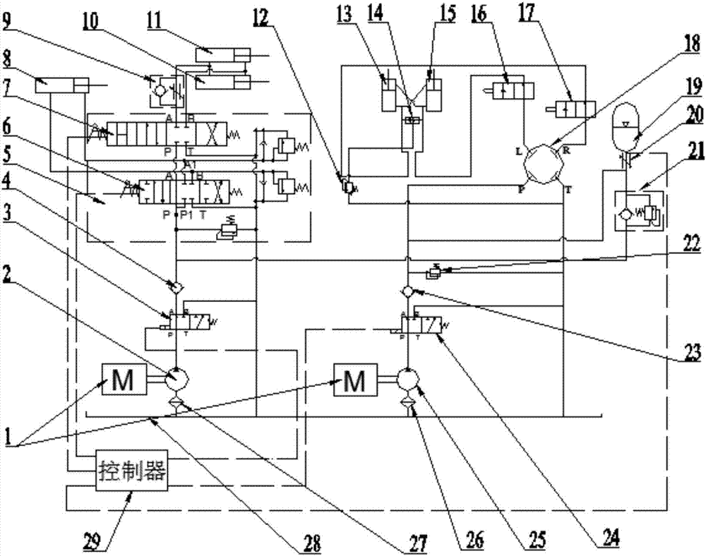
[0046] In order to further illustrate the technical solution of the present invention, in conjunction with the accompanying drawings, the specific implementation of the present invention is as follows:

[0047] Such as figure 1 As shown, the present invention provides a loader joint energy supply hydraulic system, the system includes: an engine 1, a working quantitative pump 2, a first two-position three-way reversing valve 3, a first one-way valve 4, a multi-way valve 5. Bucket cylinder 8, one-way throttle valve 9, right boom cylinder 10, left boom cylinder 11, overflow valve 12, left steering cylinder 13, shuttle valve 14, right steering cylinder 15, first limit valve 16. Second limit valve 17, closed center non-response steering gear 18, accumulator 19, throttle valve 20, one-way sequence valve 21, safety valve 22, second one-way valve 23, second two-position three-way Electromagnetic reversing valve 24, steering quantitative pump 25, first filter 26 and second filter 27, ...


PUM


Abstract

The invention provides a loader joint energy supply hydraulic system and a control method thereof. A working metering pump and a steering metering pump of the system are connected with an engine. The working metering pump is connected with a first two-position three-way reversing valve and then divided into two path through a first check valve, the first path is connected with a rotating bucket oil cylinder and a movable arm oil cylinder through a multiway valve, and the other path is connected with an energy accumulator through a check sequence valve and a throttling valve in sequence. The steering metering pump is connected with a second two-position three-way reversing valve and then divided into three path through a second check valve, the first path is connected with an oil tank through a safety valve, the second valve is connected with the energy accumulator through a throttling valve, and the third valve is connected with a closed non-response steering gear, a limiting valve and a steering oil cylinder in sequence. The control method comprises a steering judging mode and a joint action judging mode. Through the loader joint energy supply hydraulic system, joint energy supply of a steering hydraulic system and a working hydraulic system can be achieved when the working hydraulic system needs low-pressure mass flow, and the overflowing loss and throttling loss can be effectively reduced.

Description

technical field [0001] The invention belongs to the technical field of construction machinery hydraulic systems, and in particular relates to a loader combined energy supply hydraulic system and a control method thereof. Background technique [0002] Loader is a kind of engineering machinery widely used in mining, road administration, construction and other fields. The current loader hydraulic system includes quantitative system, fixed variable system and total variable system. [0003] The quantitative system has the advantages of low cost and simple structure, and is widely used in small and medium loaders. However, during the working process of the quantitative system, due to the mismatch between the output flow of the pump and the required flow of the load, the overflow loss is relatively large, resulting in a decrease in energy utilization efficiency and an increase in the temperature of the hydraulic oil, and at the same time causing the total displacement required by...

Claims


Application Information

Patent Timeline
Patent Type & Authority Applications(China)
IPC IPC(8): F15B11/16F15B1/02F15B13/06
CPCF15B1/02F15B11/16F15B13/06
Inventor 王继新张昕睿韩云武史香云王鹏于超何冠霖孙明宇
Owner JILIN UNIV
Why Eureka
Try Eureka