Insulation puncturing wire clamp and method for connecting cable by employing same

A technology of insulation puncture and clamping method, which is applied in the direction of needle tip/slotted plate contact, clamping/spring connection, connection, etc. used to penetrate insulation wire/cable core wire, which can solve the problem of difficult operation and cutting wire Cable conductors, high operator requirements, etc., to achieve the effect of a wide range of wire diameters

Active Publication Date: 2017-08-15
JIANGSU CHUANDU ELECTRICAL TECH
View PDF4 Cites 4 Cited by
  • Summary
  • Abstract
  • Description
  • Claims
  • Application Information

AI Technical Summary

Problems solved by technology

The insulation puncture clamp of this structure is fixedly connected between the puncture blade and the shell, the diameter range of the cable connected by the same specification clamp is small, and the error range of the torque nut’s fall-off torque is large, the cable diameter within the specified range Different from the contact strength of the piercing blade, there will be problems with poor contact or the piercing blade cutting off the cable conductor
In addition, the upper shell and the lower shell are clamped by bolts and nuts. When installing and connecting on site, one operator needs both hands to fix the cables and connect and lock the bolts and nuts. High standard

Method used


Image

  • Insulation puncturing wire clamp and method for connecting cable by employing same
  • Insulation puncturing wire clamp and method for connecting cable by employing same
  • Insulation puncturing wire clamp and method for connecting cable by employing same

Examples


Embodiment 1

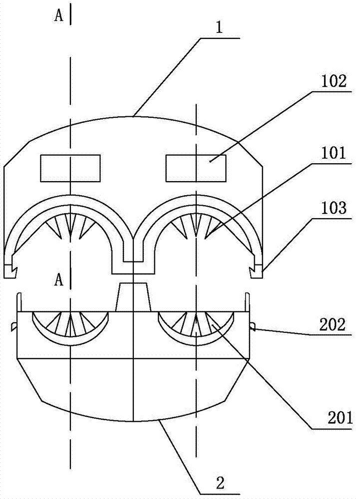
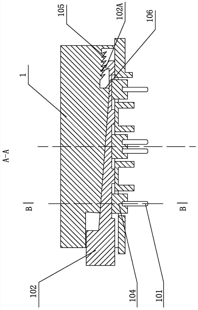
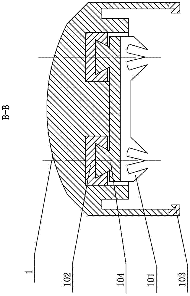
[0020] like figure 1 — image 3 As shown, it is the insulating piercing wire clip of the present invention, which includes an upper casing 1 and a lower casing 2 that are matched and docked. There is an upper piercing blade 101 that runs through the two upper half grooves and an elastic pad that matches the shape of the lower side of the upper casing 1 and facilitates the passage of the upper piercing blade 101; the upper side of the lower casing 2 is provided with a lower half corresponding to the upper half groove. Groove, the position corresponding to the upper puncture blade 101 in the lower casing is fixedly provided with the lower puncture blade 201 and matches with the shape of the upper side of the lower casing 2 and facilitates the lower puncture blade to pass through the elastic pad; the upper casing 2 and the lower casing 3 cooperate The outer sides of the butt joint are equipped with elastic buckles; the elastic buckles include elastic hooks 103 arranged on the lo...

Embodiment 2

[0024] like Figure 4 As shown, the clamping method for connecting insulated cables by using the above-mentioned insulation puncture clamp includes the following steps: 1) filling the arc-shaped half grooves of the upper casing 1 and the lower casing 2 with waterproof silicone and elastic pads respectively, Then put the main cable and the branch cable into the lower half groove of the lower casing 2 respectively and align the cables with the lower piercing blade 201 in the lower half groove, and then match the upper casing 1 with the lower casing 2 Docking and pre-tightening through the elastic buckle. At this time, the wedge-shaped extrusion block 102 in the upper housing is at the initial position, that is, the barb is at the inner step;

[0025]2) Clamp the upper housing 1 with the special clamping tool 3, push the wedge-shaped extrusion block 102 to slide inside the upper housing 1, and at the same time, the wedge-shaped extrusion block 102 pushes the upper puncture blade ...


PUM


Abstract

The invention relates to an insulation puncturing wire clamp and a method for connecting a cable by employing the same. The insulation puncturing wire clamp comprises an upper shell and a lower shell, wherein upper puncturing cutter blades and an elastic cushion are arranged in the upper shell, the elastic cushion is matched with the shape of a lower side surface of the upper shell and is used for the upper puncturing wire clamps to conveniently pass through, lower puncturing wire clamps and an elastic cushion are arranged in the lower shell, the elastic cushion is matched with the shape of an upper side surface of the lower shell and is used for the lower puncturing wire clamps to conveniently pass through, elastic buckles are arranged at two outer sides, which are abutted in a matching way, of the upper shell and the lower shell in a matching way, a sliding block is fixedly arranged at an upper side edge where the upper puncturing cutter blades and the upper shell are connected, wedge-shaped extrusion blocks are arranged in the upper shell at an upper side of the sliding block in a matching way, can slide leftwards and rightwards and can be used for upwards and downwards extruding the puncturing cutter blades, extrusion surfaces are arranged in the upper shell at upper sides of the wedge-shaped extrusion blocks and are matched with wedge-shaped surfaces of the wedge-shaped extrusion blocks, the sliding block is pushed to drive the puncturing cutter blades to move downwards when the wedge-shaped extrusion blocks slides inwards from an outer side of the upper shell, and backward prevention mechanism are arranged at tail ends of the wedge-shaped extrusion blocks and tail ends of the corresponding extrusion surfaces of the upper shell.

Description

technical field [0001] The invention relates to the technical field of electric power fittings, in particular to an insulation piercing clamp which is convenient for clamping, and is used for quick connection of branches or continuous lines of insulated cables. Background technique [0002] The insulating piercing clamp in the prior art includes an upper shell and a lower shell, the upper shell is fixed with an upper piercing blade, the lower shell is equipped with a lower piercing blade, and the mating surface of the upper shell and the lower shell is provided with a seal. High-strength bolts and torque nuts are arranged between the gasket, the waterproof silicone grease, the upper shell and the lower shell, and the torque nuts are connected with lock nuts to form a nut assembly. When the cable needs to be branched or continued, clamp the main cable and the branch cable between the piercing blades of the upper and lower shells of the insulation piercing clamp, penetrate the...

Claims


Application Information

Patent Timeline
Patent Type & Authority Applications(China)
IPC IPC(8): H01R4/24H01R4/48H01R4/50
CPCH01R4/2412H01R4/48H01R4/5083
Inventor 孙杰孙义忠张伟
Owner JIANGSU CHUANDU ELECTRICAL TECH
Why Eureka
Try Eureka