Upper sill door head assembly equipment for elevator

An assembly equipment and the technology of the gate head, which is applied in the field of elevators, can solve the problems that the gap between the track and the roller is too large or too small, which affects the service life and safety performance of the upper gate head, and achieves the effect of prolonging the service life

Active Publication Date: 2017-08-18
NINGBO LILONG ELECTROMECHANICAL
View PDF5 Cites 0 Cited by
  • Summary
  • Abstract
  • Description
  • Claims
  • Application Information

AI Technical Summary

Problems solved by technology

The existing upper sill head includes an upper sill with horizontal guide rails and a door hanging plate linked with the landing door. There are two door hanging plates and they are all slidably connected to the slide rails through rollers. The single door hanging plate There are multiple rollers placed above and below the slide rail. There are linkage components that can be moved closer or separated in reverse and interlocking knuckle components between the two door hanging plates. Matching inserted grooves and convex strips make the door hanging plate movably connected to the upper sill through the rollers, which not only guides the horizontal translation of the door hanging plate, but also ensures the stable hanging of the door hanging plate on the upper sill On the board, in order for the roller to achieve the above purpose, during installation, the roller should not only be fixed with the door hanging plate, but also prevent it from detaching from the track, and prevent the roller from clamping the track too tightly to affect the movement of the door hanging plate, reducing wear and tear. Therefore, when assembling the rollers, it is necessary to precisely position the relative positions of the rollers, the upper sill, and the door hanging plate to ensure the normal use of the upper sill head. However, there are large errors in the existing assembly method, and the gap between the track and the rollers is too large. The problem of being too big or too small will affect the service life and safety performance of the upper canopy head

Method used


Image

  • Upper sill door head assembly equipment for elevator
  • Upper sill door head assembly equipment for elevator
  • Upper sill door head assembly equipment for elevator

Examples


Embodiment Construction

[0020] The substantive features of the present invention will be further described below in conjunction with the accompanying drawings and specific embodiments.

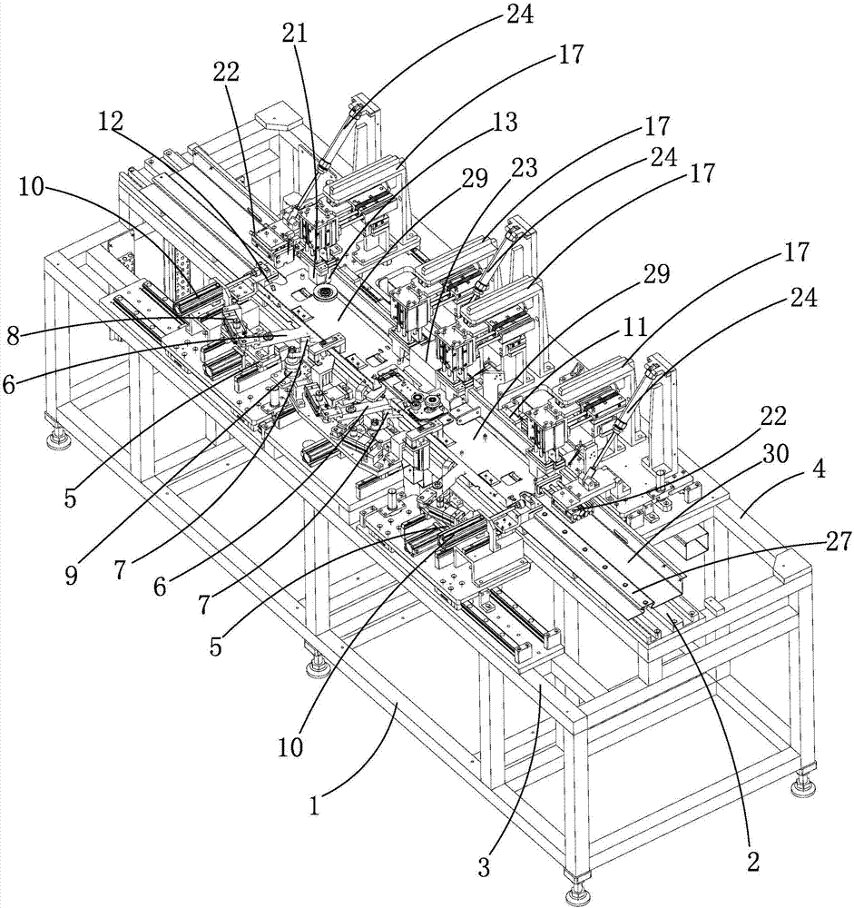
[0021] Such as figure 1 The shown assembly equipment for the upper gate head of an elevator is composed of a frame 1 and an installation platform 2 located on the top surface of the frame 1. The edge 4 is provided with a first positioning structure, a second positioning structure and a third positioning structure for respectively positioning the upper rocker 30, the door hanging plate 29 and the roller 28, so that the roller 28 is positioned between the track 27 of the upper rocker 30. On the installation station with equal height and 0.2mm-0.5mm longitudinal gap reserved.

[0022] When in use, the first positioning structure is used to fix the upper sill 30, the second positioning structure is used to fix the door hanging plate 29, and the third positioning structure is used to fix the roller 28, so that the upper ...


PUM


Abstract

The invention relates to upper sill door head assembly equipment for an elevator. Longitudinal clearance between a roller for existing production link and a rail cannot meet design requirements, so that a condition of serious abrasion or extremely easy separation appears. The upper sill door head assembly comprises a rack and a mounting platform, wherein a first positioning structure, a second positioning structure and a third positioning structure are arranged on a front edge part and a rear edge part, so that the roller is positioned onto a mounting station which is as high as a rail of an upper sill plate and is reserved with a longitudinal gap of 0.2mm-0.5mm. In case of reserving the longitudinal gap with the rail, the roller is fixedly connected with a door hanging plate, so that the roller and the door hanging plate do not derail as a result of too great gap between the roller and the rail, the door hanging plate and the upper sill plate can be precisely and fixedly connected onto the mounting station of a landing door after being mounted, and the roller and the rail further can be guaranteed to be free of a severe wear condition as a result of tight fit, and therefore, the service life of an upper sill door head is effectively prolonged.

Description

technical field [0001] The invention relates to the field of elevators, in particular to a production equipment. Background technique [0002] Van elevators are widely used in high-rise or multi-storey buildings, which is convenient for people to go up and down floors. In the existing elevator structure, the upper rocker head completes the action of opening and closing the landing door under the action of the door machine. The existing upper sill head includes an upper sill with horizontal guide rails and a door hanging plate linked with the landing door. There are two door hanging plates and they are all slidably connected to the slide rails through rollers. The single door hanging plate There are multiple rollers placed above and below the slide rail. There are linkage components that can be moved closer or separated in reverse and interlocking knuckle components between the two door hanging plates. Matching inserted grooves and convex strips make the door hanging plate ...

Claims


Application Information

Patent Timeline
Patent Type & Authority Applications(China)
IPC IPC(8): B23P21/00
CPCB23P21/002
Inventor 顾益辉伍鹏张君龙
Owner NINGBO LILONG ELECTROMECHANICAL
Why Eureka
Try Eureka