High-speed rail transit device

A high-speed track and transportation technology, applied in the field of track devices and high-speed rail transit devices, can solve the problems of slow speed, small space for speed improvement of wheel-rail high-speed rail and maglev high-speed rail, and low efficiency, so as to achieve the effect of improving lift

Active Publication Date: 2022-01-04
王全文
View PDF7 Cites 1 Cited by
  • Summary
  • Abstract
  • Description
  • Claims
  • Application Information

AI Technical Summary

Problems solved by technology

[0006] The technical problem to be solved by the present invention is to provide a high-speed rail transit device and its supporting rail device to solve the slow speed and low efficiency of ordinary trains in the prior art, and the lack of space for speed improvement in wheel-rail high-speed rail and maglev high-speed rail. Large and difficult problems of the vacuum tunnel maglev super high-speed rail technology under development

Method used


Image

  • High-speed rail transit device
  • High-speed rail transit device
  • High-speed rail transit device

Examples


Embodiment 1

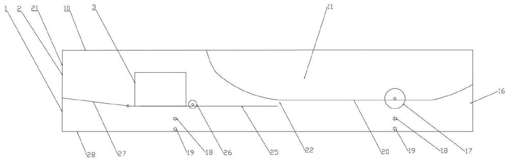
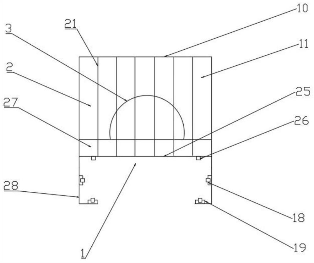
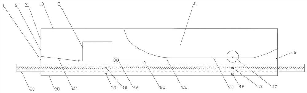
[0071] The invention provides a high-speed rail transit device, such as Figure 1-3As shown, it includes three parts: the power chamber, the rail-holding suspension chamber, and the passenger and cargo compartment. Fuel room, etc.; the power chamber is set between the passenger and cargo compartment and the rail-holding suspension chamber, and is surrounded by the power chamber bottom plate 25, the passenger and cargo compartment floor 20, the rail-holding wind plate 27 and the shell 10, and the front end opening of the power chamber forms the power chamber The air inlet 2, the rear end opening forms the lower nozzle 22 of the power chamber, the air inlet of the power chamber reduces the air suction wind resistance of the front of the car, and the speed is faster than the land maglev super high-speed rail under normal atmospheric pressure. The lower nozzle of the power chamber is reserved between the floor of the power chamber and the floor of the cargo compartment. In order t...

Embodiment 2

[0080] A kind of high-speed rail transit device of the present invention comprises upper air channel 9, as Figure 7-8 As shown, the upper airway is arranged on the upper part of the cargo compartment, its front end is connected to the power chamber, and the rear end opens to form an upper nozzle 14 .

[0081] Such as Figure 11-13 As shown, there is a top installation hole on the top of the upper air passage, and a lifting force adjustment plate is rotatably installed on the top installation hole. The lifting force adjustment plate can be rotated at an angle of ±90 degrees; A set of side mounting holes, in which a lateral force adjustment plate is rotatably installed, and the lateral force adjustment plate can be rotated at an angle of ±45 degrees.

[0082] All the other structures of embodiment 2 are the same as embodiment 1. The tail nozzle and the upper nozzle in Embodiment 2 of the present invention are respectively rotatably provided with a nozzle regulating plate 15, ...

Embodiment 3

[0084] A high-speed rail transit device of the present invention includes two upper air passages 45, as shown in Figures 9-10, the two upper air passages are respectively arranged on both sides of the upper part of the passenger and cargo compartment, and the front ends of the two upper air passages All are connected to the power chamber, and the rear ends are all open to form the upper spout 46 on the side.

[0085] Such as Figure 11-13 As shown, the top of the side upper airway is provided with a top mounting hole, and the lifting force adjustment plate 47 is rotatably installed on the top mounting hole, and the rotatable angle of the lifting force adjustment plate is ±90 degrees; the two sides of the side upper airway are symmetrical At least one set of side mounting holes is provided, and a lateral force regulating plate 48 is rotatably installed in the side mounting holes, and the rotatable angle of the lateral force regulating plate is ±45 degrees.

[0086] All the oth...


PUM


Abstract

The invention relates to a high-speed rail transit device which comprises a power cavity, a rail-holding suspension cavity and a passenger and cargo compartment, and is characterized in that the passenger and cargo compartment is of a compartment body structure; the power cavity is arranged between the passenger and cargo compartment and the rail-holding suspension cavity and is defined by a power cavity bottom plate, a passenger and cargo compartment bottom plate, a rail-holding windward plate and a shell, a power cavity air inlet is formed by an opening in the front end of the power cavity, a power cavity lower nozzle is formed by an opening in the rear end of the power cavity, the power cavity lower nozzle is reserved between the power cavity bottom plate and the passenger and cargo compartment bottom plate, the power cavity air inlet is further provided with a protective grating, and the area of the power cavity air inlet is larger than that of the power cavity lower nozzle. According to the high-speed rail transit device, the front end of a jet sucks air from the air inlet of the power cavity and then jets high-pressure air from the lower nozzle of the power cavity, the high-pressure air flows between the passenger and cargo compartment and the rail device, and an air cushion is formed between the passenger and cargo compartment and the rail device due to exhaust limitation and high air pressure to generate lift force and advancing power.

Description

technical field [0001] The invention relates to the technical field of rail transportation tools, in particular to a high-speed rail transportation device and a matching rail device. Background technique [0002] Existing rail vehicles include ordinary trains, wheel-rail high-speed rail, and maglev high-speed rail. In order to further increase the speed, the vacuum tunnel maglev super high-speed rail is currently being developed. The goal is to achieve a high-speed operation of more than 350km / h. Ordinary trains are powered by electricity or steam engines and move forward through the rotation of the wheels, which is slow and inefficient; wheel-rail high-speed railways are powered by electricity and still move forward through fast rotation of the wheels. Due to the restriction of the wheel speed and the unfavorable factors of contact friction with the track, there is not much room for further increase in speed; the magnetic levitation high-speed rail uses electric power to pr...

Claims


Application Information

Patent Timeline
Patent Type & Authority Applications(China)
IPC IPC(8): B61B13/10B61B13/08B61B13/12
CPCB61B13/10B61B13/08B61B13/122Y02T30/00
Inventor 王全文
Owner 王全文
Why Eureka
Try Eureka