Film removing method for high light plate piece

A high-gloss plate and plate technology, applied in the field of auto parts processing, can solve problems such as tape waste

Active Publication Date: 2017-08-18
徐州博枫木业有限公司
View PDF4 Cites 2 Cited by
  • Summary
  • Abstract
  • Description
  • Claims
  • Application Information

AI Technical Summary

Problems solved by technology

[0003] The present invention intends to provide a film-removing method for high-gloss boards, so as

Method used


Image

  • Film removing method for high light plate piece
  • Film removing method for high light plate piece

Examples


Embodiment Construction

[0019] The present invention will be described in further detail below by means of specific embodiments:

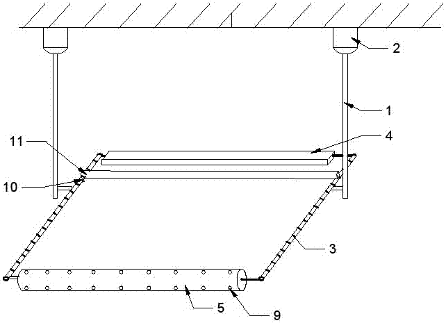
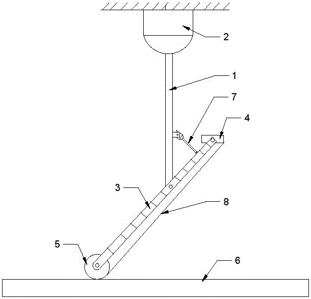
[0020] The reference signs in the drawings of the description include: support rod 1, first cylinder 2, telescopic shaft 3, mucous membrane plate 4, counterweight cylinder 5, high-gloss plate 6, transmission cylinder 7, protective film 8, communication hole 9, cutting Film cutter 10, guide rail 11.

[0021] The film-removing method used for high-gloss boards in this solution includes the following steps:

[0022] Step 1: Prepare the film removal device, which is attached figure 1 , figure 2 As shown: it includes a frame, a stripping mechanism and a support. The support is composed of two struts 1. The upper ends of the two struts 1 are fixedly connected with the first cylinder 2, and the first cylinder 2 slides horizontally on the frame. The lower end of the bracket is connected to the stripping mechanism.

[0023] The stripping mechanism includes a mucous membrane p...


PUM

PropertyMeasurementUnit
Rotation angleaaaaaaaaaa

Abstract

The invention relates to a film removing method for a high light plate piece. A rack, a film stripping mechanism and a bracket horizontally and slidably connected on the rack are included; one end of the bracket is connected with a reciprocating transmission mechanism, and the other end of the bracket is connected to the film stripping mechanism; the film stripping mechanism comprises a film pasting plate, a counterweight drum and two telescopic shafts hinged to the bracket; transmission air cylinders are connected between the bracket and the telescopic shafts; the film pasting plate and the counterweight drum are parallelly mounted between the two telescopic shafts and are rotatably connected on the two telescopic shafts; a negative pressure cavity is formed in the counterweight drum; communicating holes communicating with the negative pressure cavity are formed in the counterweight drum; film cutting cutters are mounted at the ends, close to the film pasting plate, of the telescopic shafts; and the movement tracks of the film cutting cutters are parallel to the film pasting plate. Through implementation of the technical scheme, the effects of environmental protection and high efficiency in the film removing process is guaranteed.

Description

technical field [0001] The invention relates to the field of auto parts processing, in particular to a film-removing method for high-gloss plate parts. Background technique [0002] At present, some high-end automotive panels use high-gloss panels, and such high-gloss panels need to be attached with a protective film on the surface and then assembled with other parts to avoid scratches. After the assembly is completed, the protective film needs to be torn off . In order to achieve mass production and rapid production, flow operations are generally carried out on the conveyor belt, so the existing method of separating the protective film generally does not use mechanical methods, because the high-gloss board needs to be fixed during separation, but it is not easy to separate the board during the transmission process. Fixed, even if it is fixed on the conveyor belt, it must be separated later, which lengthens the steps. The common method is manual separation, that is, worker...

Claims


Application Information

Patent Timeline
IPC IPC(8): B65B69/00
CPCB65B69/0033
Inventor 陈勇
Owner 徐州博枫木业有限公司
Why Eureka
Try Eureka