
Intelligent hangar for unmanned plane

A smart hangar and UAV technology, which is applied in the direction of parking buildings, building types, buildings, etc., can solve the problems of low solar conversion rate, long working hours, UAV working environment and work task restrictions, etc. Achieve the effect of prolonging battery life and ensuring normal operation

Pending Publication Date: 2017-08-18
上海巨什机器人科技有限公司
View PDF0 Cites 20 Cited by
  • Summary
  • Abstract
  • Description
  • Claims
  • Application Information

AI Technical Summary

Problems solved by technology

[0003] However, the battery life of drones has become the biggest bottleneck hindering the development of drones. Although lithium-ion batteries are currently the best battery in the market, they still cannot fully meet the needs of drones: solar batteries are because of drones. Due to the small surface area and low solar energy conversion rate, it cannot meet the working needs of drones.
At present, after the power of the drone is exhausted, it needs to return to the artificial site to renew the power of the drone. Usually, the drone can only choose a location close to the artificial site to work, but the artificial site is limited by the environmental location. As a result, the working environment and tasks of UAVs are restricted, and tasks that are not suitable for artificial sites or that are far away from artificial sites will not be completed, and UAVs cannot be used in wider areas
[0004] Therefore, how to increase the endurance of UAVs so that UAVs can be used in different environments and accept a large number of tasks such as long working hours is a technical problem to be solved at present.

Method used


Image

  • Intelligent hangar for unmanned plane
  • Intelligent hangar for unmanned plane
  • Intelligent hangar for unmanned plane

Examples


Embodiment Construction

[0024] In order to make the object, technical solution and advantages of the present invention clearer, various embodiments of the present invention will be described in detail below in conjunction with the accompanying drawings. However, those of ordinary skill in the art can understand that, in each implementation manner of the present invention, many technical details are provided for readers to better understand the present application. However, even without these technical details and various changes and modifications based on the following implementation modes, the technical solution claimed in this application can also be realized.

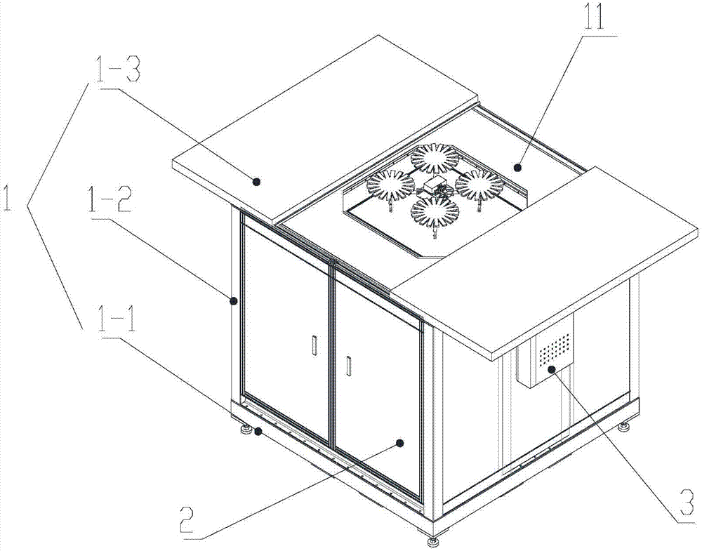
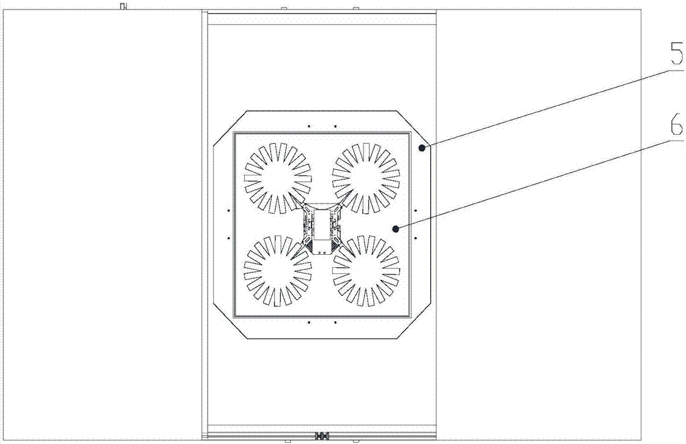
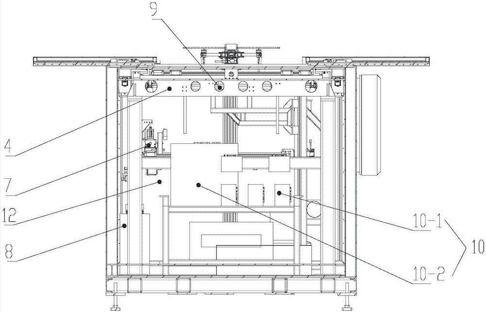
[0025] The first embodiment of the present invention relates to an unmanned aerial vehicle intelligent hangar, such as figure 1 , figure 2 , image 3 , Figure 4 and Figure 5 As shown, it is powered by the daily power supply system and includes a library body 1. The library body 1 includes a bottom 1-1, a side wall 1-2 surrounding the...


PUM


Abstract

The invention relates to the field of unmanned aerial vehicle equipment, and discloses an intelligent hangar for unmanned aerial vehicles, powered by a daily power supply system, including a warehouse body, a bottom, a side wall surrounding the bottom to form an accommodation cavity, and a door opening mechanism; a manipulator mechanism , in exchange for the battery of the drone; the lifting parking platform, which moves up and down in the accommodating cavity; the fixed parking platform, which is set opposite to the bottom, and is located on the side of the door switch mechanism, the fixed parking platform, the parking area for parking the drone and the parking area The notch in the middle of the area; the preliminary positioning mechanism, positioning or moving the drone to the lifting platform; the battery charging tool, with multiple charging positions for charging the battery of the drone; the backup power supply system, in the daily power supply system Temporary power supply for UAV smart hangar in case of power outage; control system. Compared with the existing technology, the endurance of the UAV is increased, so that the UAV can be used in different environments, and it can accept a large number of tasks such as long working hours.

Description

technical field [0001] The invention relates to the field of unmanned aerial vehicle equipment, in particular to an intelligent hangar for unmanned aerial vehicles. Background technique [0002] With the deepening of recognition of the application value of drones, drones are showing rapid development in the consumer, industrial and military markets. UAVs are increasingly used in aerial photography, agriculture, forestry and plant protection, security, surveying and mapping, logistics, inspection and other fields. [0003] However, the battery life of drones has become the biggest bottleneck hindering the development of drones. Although lithium-ion batteries are currently the best battery in the market, they still cannot fully meet the needs of drones: solar batteries are because of drones. Due to the small surface area and low solar energy conversion rate, it cannot meet the working needs of drones. At present, after the power of the drone is exhausted, it needs to return ...

Claims


Application Information

Patent Timeline
Patent Type & Authority Applications(China)
IPC IPC(8): E04H6/44
CPCE04H6/44
Inventor 张政印徐志华周清
Owner 上海巨什机器人科技有限公司
Learn More