
Pressure barrel of RO water purifier

A pressure tank and water purifier technology, applied in the direction of pressure vessels, functional valve types, gas/liquid distribution and storage, etc., can solve the problems of poor safety of pressure tanks, and achieve the effect of reducing material usage and cost

Active Publication Date: 2017-08-18
玉环昕旺科技有限公司
View PDF6 Cites 2 Cited by
  • Summary
  • Abstract
  • Description
  • Claims
  • Application Information

AI Technical Summary

Problems solved by technology

[0004] The purpose of the present invention is to solve the problem of poor safety of the existing pressure tank, and provide a pressure tank of RO water purifier. When the water in the pressure tank is filled up to generate water injection pressure, the pressure limiting valve closes the water inlet, thereby limiting The pressure in the barrel continues to increase to prevent the pressure barrel from bursting; when the external pressure of water injection is removed, it will automatically open and become normally open

Method used


Image

  • Pressure barrel of RO water purifier
  • Pressure barrel of RO water purifier
  • Pressure barrel of RO water purifier

Examples


Embodiment 1

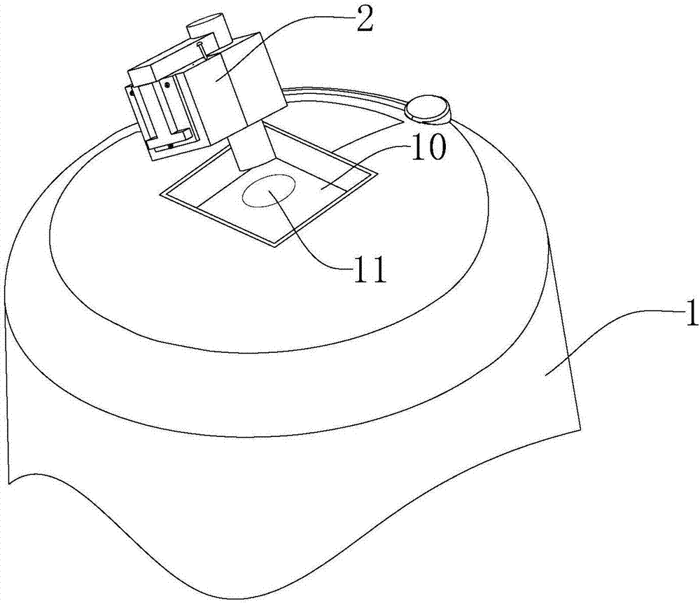
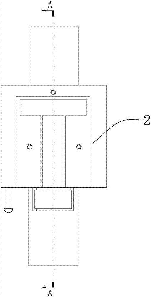
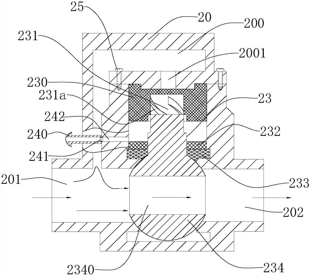
[0024] Such as Figures 1 to 5 The shown pressure barrel used in the water purification system includes a pressure barrel body 1, a pressure limiting valve installation groove 10 is provided on the top of the pressure barrel body 1, and a pressure limiting valve installation groove 10 is opened for water to enter the barrel. Inside the inlet and outlet 11, the pressure limiting valve 2 is packed into the pressure limiting valve installation groove 10 and the pipe at the output end stretches into the inlet and outlet 11. Wherein the pressure limiting valve 2 is a normally open valve that can automatically close and cut off the water injection when exceeding a certain injection water pressure threshold, and automatically open the water outlet when it is lower than the threshold. Its specific structure is as follows:

[0025] The pressure limiting valve 2 includes a valve seat 20 , a ball valve spool 234 and a piston assembly 23 for driving the ball valve spool to rotate. The v...


PUM


Abstract

The invention belongs to the field of household water purifiers and particularly relates to a pressure barrel of an RO water purifier. The pressure barrel of the RO water purifier comprises a pressure barrel body, the top end of the pressure barrel body is provided with a feeding / discharging opening, and the feeding / discharging opening is furthermore provided with pressure limiting valve for preventing overpressure; the pressure limiting valve comprises a valve seat, a ball valve core and a piston assembly for driving the ball valve core to rotate; the piston assembly comprises a permanent magnetic piston, a valve rod for driving the ball valve core to rotate and a permanent magnetic pressing ring; one end of the valve rod is fixedly connected with the ball valve core, the other end of the valve rod is in rotation fit with the permanent magnetic piston, and the permanent magnetic pressing ring is arranged outside the valve rod in a sleeve manner; the permanent magnetic piston corresponds to the permanent magnetic pressing ring in position, and the magnetic pole of the permanent magnetic piston is repulsive to the magnetic pole of the permanent magnetic pressing ring; and the permanent magnetic piston is installed in a piston assembly installation cavity in a sealed manner, and the pressure input face faces the output end of a bypass passage. According to the pressure barrel, when the pressure barrel is filled with water to generate water injection pressure, the pressure limiting valve turns off a water inlet, so that continuous increase of the pressure in the barrel is limited, and cracking of the pressure barrel is prevented.

Description

technical field [0001] The invention belongs to the field of household water purifiers, in particular to a water storage pressure barrel in an RO water purifier. Background technique [0002] The pressure tank is mainly used to store water in household RO water purifiers, and generally bears relatively high pressure. With the fierce competition, the price of pressure barrels has dropped, and plastic barrels have continued to replace steel barrels. In the existing market, in order to save costs, the plastic wall of the plastic pressure barrel is made relatively thin. Due to the influence of the manufacturing process and the overload of water storage, the plastic pressure tank will gradually expand. Every year, there will be plastic pressure tanks that are difficult to withstand pressure and cause explosions, causing danger to the home kitchen and causing huge compensation losses for the manufacturer. [0003] However, facing the pressure of competition, many manufacturers a...

Claims


Application Information

Patent Timeline
Patent Type & Authority Applications(China)
IPC IPC(8): F16J12/00F16K17/00F16K37/00
CPCF16J12/00F16K17/00F16K37/0066
Inventor 周孝银
Owner 玉环昕旺科技有限公司
Learn More