External optical orientation equipment and orientation method thereof

A technology of optical orientation and optical equipment, which is applied in the directions of measuring devices, measuring angles, surveying and navigation, etc., can solve the problems of difficulty in installation and insufficient measurement accuracy, and achieve the purpose of overcoming the lack of processing and installation accuracy and ensuring the accuracy of alignment. The effect of enhancing flexibility and variety

Active Publication Date: 2017-08-18
AIR FORCE EARLY WARNING ACADEMY
View PDF4 Cites 5 Cited by
  • Summary
  • Abstract
  • Description
  • Claims
  • Application Information

AI Technical Summary

Problems solved by technology

[0004] In view of the above defects or improvement needs of the prior art, the present invention provides an external optical orientation device and a direction finding method, the purpose of which is to realize the measurement of the azimuth angl...

Method used


Image

  • External optical orientation equipment and orientation method thereof
  • External optical orientation equipment and orientation method thereof
  • External optical orientation equipment and orientation method thereof

Examples


Embodiment Construction

[0037] In order to make the object, technical solution and advantages of the present invention clearer, the present invention will be further described in detail below in conjunction with the accompanying drawings and embodiments. It should be understood that the specific embodiments described here are only used to explain the present invention, not to limit the present invention. In addition, the technical features involved in the various embodiments of the present invention described below can be combined with each other as long as they do not constitute a conflict with each other.

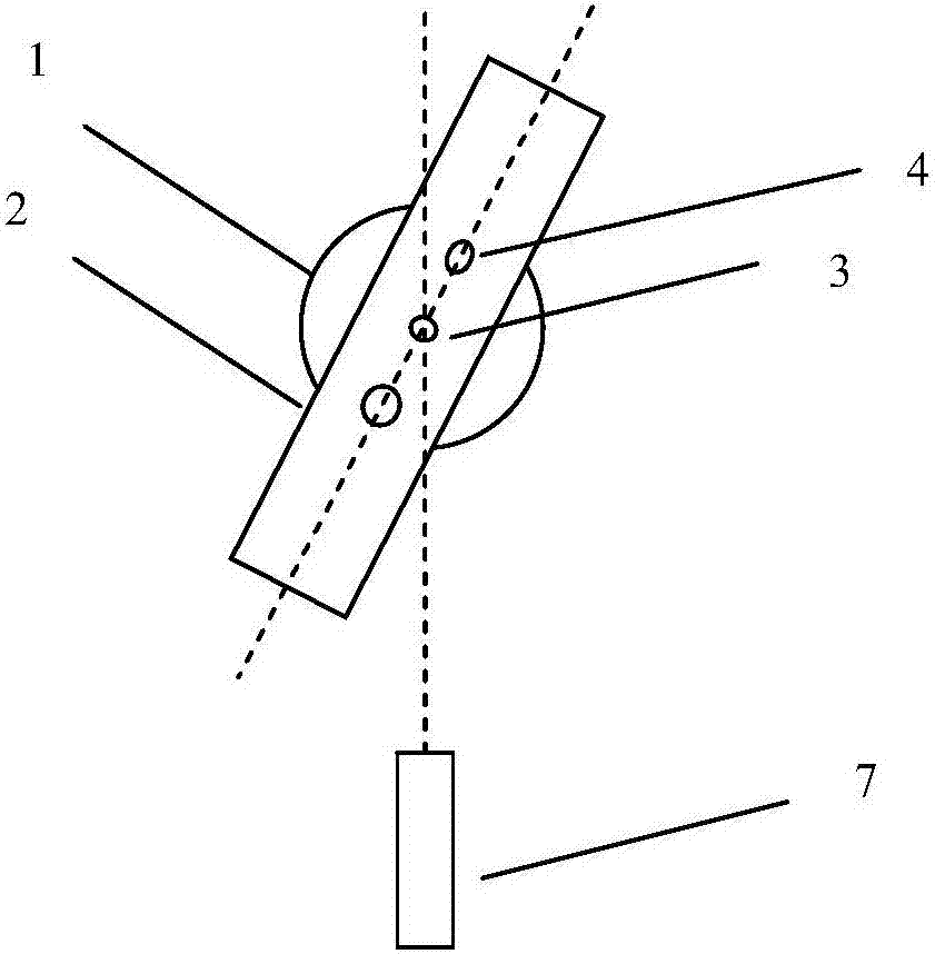
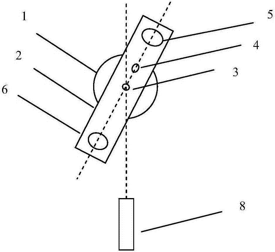
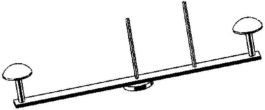
[0038] Based on the measurement of the azimuth angle of the center line of the direction-finding optical equipment to be measured by the direction-finding device, the invention designs a set of external rotating mechanical devices, which solves the problem of fast and accurate alignment of the optical axis. It can be set up on an outdoor open space with a tripod or a vehicle frame to measure the...


PUM


Abstract

The invention discloses external optical orientation equipment. The external optical orientation equipment comprises an antenna substrate, a first marking pole, a second marking pole and an orientation device, wherein the antenna substrate is rotationally mounted on a rotary plate and is coaxial with the center of the rotary plate; the first marking pole is fixedly mounted on the antenna substrate and is coaxial with the antenna substrate and the center of the rotary plate; the second marking pole is fixedly mounted on the antenna substrate, and the distance between the second marking pole and the first marking pole is larger than a first set distance threshold value; the orientation device is fixedly mounted on the antenna substrate, the center of the orientation device is located on the connection line of the first marking pole and the second marking pole, and the orientation device is used for measuring the azimuth angle of the connection line of the first marking pole and the second marking pole. The external optical orientation equipment is independent of to-be-oriented optical equipment and can be repeatedly used; aligning precision can be guaranteed with the adoption of optical aligning. The invention further provides a corresponding orientation method.

Description

technical field [0001] The invention belongs to the technical field of optical orientation, and more specifically relates to an external optical orientation device and a direction-finding method thereof. Background technique [0002] In general, the orientation scheme of optical instruments and equipment is usually to connect the orientation equipment including electronic compass or fiber optic gyroscope and other direction finding devices to the optical instruments. Due to the high price of directional equipment, many optical instruments and equipment are not equipped with directional equipment during design. However, when needed in later applications, it is generally more difficult to install directional equipment, and it is also more troublesome to detect and replace the instrument performance of directional equipment. [0003] Furthermore, the currently adopted fixing solution is usually to align the direction-finding device with the axis base line of the housing of the...

Claims


Application Information

Patent Timeline
IPC IPC(8): G01C1/00G01C17/32G01C19/72G01S19/53
CPCG01C1/00G01C17/32G01C19/72G01S19/53
Inventor 王良斯冷毅罗威董文锋杨华兵何缓贺昌辉
Owner AIR FORCE EARLY WARNING ACADEMY
Why Eureka
Try Eureka