
Temperature transmitter measurement error intelligent verification and analysis system

A temperature transmitter and measurement error technology, which is applied in thermometer testing/calibration, thermometer, heat measurement, etc., can solve problems such as long calibration time, accuracy impact, fatigue operation, etc., to improve calibration speed and improve calibration efficiency effect

Inactive Publication Date: 2017-08-18
STATE GRID FUJIAN ELECTRIC POWER CO LTD +2
View PDF13 Cites 8 Cited by
  • Summary
  • Abstract
  • Description
  • Claims
  • Application Information

AI Technical Summary

Problems solved by technology

At present, the annual inspection workload of temperature transmitters is heavy
At present, the existing temperature transmitter calibration instrument can only calibrate a single transmitter at a time, and requires manual real-time operation and recording, and the calibration time is long; at the same time, the temperature transmitter required for calibration every year The number of temperature transmitters is large. When calibrating multiple temperature transmitters, on the one hand, it is easy to affect the accuracy of the portable temperature transmitter calibrator; When the transmitter is inspected, dedicated personnel need to be invested, which consumes manpower, and repeated operations for a long time will easily lead to fatigue operation, which will bring hidden dangers of safety accidents
[0003] Nowadays, the development of science and technology has led to more and more smart devices and systems being used in large quantities, but the company's current method of testing and verifying devices is still stuck in decades ago, failing to keep up with the pace of technological development

Method used


Image

  • Temperature transmitter measurement error intelligent verification and analysis system
  • Temperature transmitter measurement error intelligent verification and analysis system

Examples


Embodiment

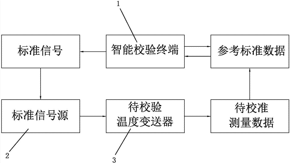
[0026] The operating principle of the intelligent verification system of the present invention can be found in figure 1 As shown, the intelligent verification terminal 1 generates a standard signal, and transmits the standard signal to the standard signal source 2, through which the standard signal source 2 converts the corresponding standard resistance signal, standard voltage signal and standard current signal, and the temperature to be verified The transmitter 3 takes the standard signal source 2 as input, and outputs measurement data with calibration. The measurement data to be calibrated is compared with the reference standard data, and the intelligent calibration terminal 1 calculates and obtains an error.

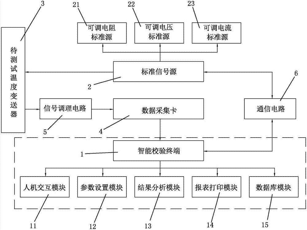
[0027] see figure 2 As shown, a temperature transmitter 3 measurement error intelligent verification analysis system of the present invention is used to verify and analyze the measurement error of the temperature transmitter 3 to be verified, including a standard s...


PUM


Abstract

The invention discloses a temperature transmitter measurement error intelligent verification and analysis system, which is used for verifying and analyzing measurement errors of a temperature transmitter to be verified. The system comprises a standard signal source, a data acquisition card and an intelligent verification terminal. The input end of the temperature transmitter to be verified is connected with the standard signal source, and the output end thereof is connected to the intelligent verification terminal through the data acquisition card. The standard signal source comprises an adjustable resistance standard source, an adjustable voltage standard source and an adjustable current standard source. The intelligent verification terminal comprises a parameter setting module and a result analysis module. The parameter setting module is used for generating a control signal according to test parameters set by a user and transmitting the control signal to the standard signal source; and the result analysis module is used for calculating the measurement errors. The provided temperature transmitter measurement error intelligent verification and analysis system realizes automatic verification of the temperature transmitter and is efficient and accurate.

Description

technical field [0001] The invention relates to an intelligent error calibration and analysis system, in particular to an intelligent calibration and analysis system for measuring the error of a temperature transmitter. Background technique [0002] A temperature transmitter is an instrument that converts a temperature variable into a transmittable standardized output signal. It is mainly used to measure the oil temperature of the main transformer of the power system. According to the requirements of the specification for the use of the temperature transmitter, it needs to be inspected periodically to ensure that the accuracy of the temperature transmitter meets the requirements. At present, the annual inspection workload of temperature transmitters is heavy. At present, the existing temperature transmitter calibration instrument can only calibrate a single transmitter at a time, and requires manual real-time operation and recording, and the calibration time is long; at the...

Claims


Application Information

Patent Timeline
IPC IPC(8): G01K15/00
CPCG01K15/007
Inventor 程祝媛许志红刘逸峰林继勇贾进民洪君毅金闪
Owner STATE GRID FUJIAN ELECTRIC POWER CO LTD
Learn More