Stand-by power supply automatic switching device

A backup power supply and automatic switching technology, which is applied in the direction of circuit devices, emergency power supply arrangements, electrical components, etc., can solve the problems of unable to set the switching threshold and repeatedly alternately switch power supply, so as to achieve stable power supply and eliminate repeated alternate switching Effect

Inactive Publication Date: 2017-08-18
AEROSPACE HI TECH HLDG GROUP
View PDF4 Cites 2 Cited by
  • Summary
  • Abstract
  • Description
  • Claims
  • Application Information

AI Technical Summary

Problems solved by technology

[0009] The purpose of the present invention is to solve the problem that although the existing switching circuit can automatically switch to the

Method used


Image

  • Stand-by power supply automatic switching device
  • Stand-by power supply automatic switching device
  • Stand-by power supply automatic switching device

Examples


specific Embodiment approach 1

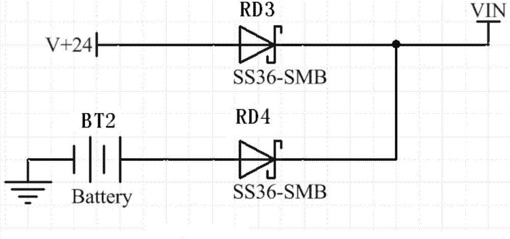
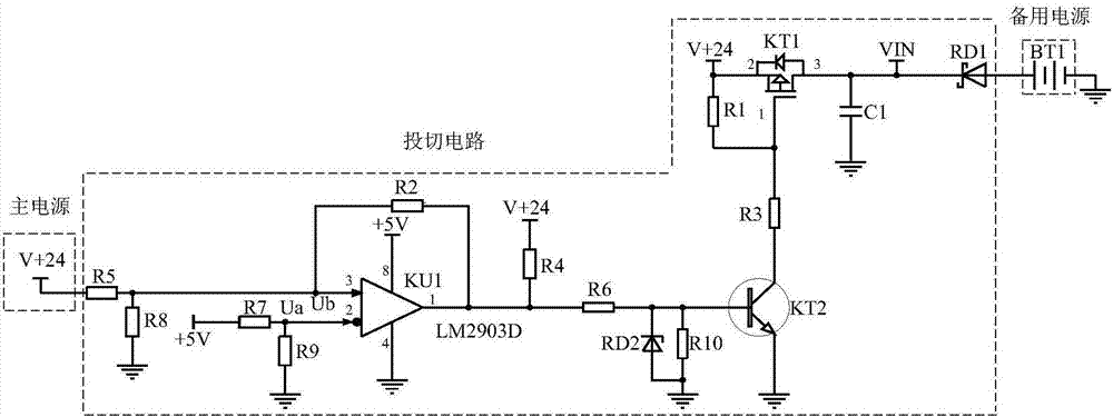
[0033] Specific implementation mode one: refer to figure 1 Specifically illustrate this embodiment, the backup power automatic switching circuit described in this embodiment, it includes main power supply, backup power BT1 and switching circuit;

[0034] The switching circuit includes resistors R1-R10, anti-reverse diode RD1, regulator tube RD2, PMOS tube KT1, triode KT2, capacitor C1, voltage comparator KU1 and reference voltage;

[0035] One end of the resistor R5 is connected to one end of the resistor R8, one end of the resistor R2 and the positive phase input terminal of the voltage comparator KU1, and the other end of the resistor R8 is connected to the power ground.

[0036] The other end of the resistor R5 is connected to the positive pole of the main power supply,

[0037] The inverting input terminal of the voltage comparator KU1 is connected to one end of the resistor R9 and one end of the resistor R7 at the same time, the other end of the resistor R7 is connected ...

Embodiment

[0043] The main power supply is realized by a battery, and the nominal value of the battery voltage is 24V. Note that the power supply BT1 is realized by a lithium battery, and the reference voltage is +5V power supply.

[0044] Resistor R7 and resistor R9 divide the voltage of +5V power supply, Ua=2.5V, as the input reference voltage of voltage comparator KU1. Resistor R5 and resistor R8 divide the voltage of battery BT1, and Ub is used as the input comparison voltage of the voltage comparator.

[0045] When the device is turned on, when the battery voltage is higher than 17V, the voltage comparator KU1 outputs a high level, drives the triode KT2 to conduct, drives the PMOS transistor KT1 to conduct, and VIN is powered by the battery. The anti-reverse diode RD1 can prevent VIN from applying reverse voltage to the lithium battery at this time.

[0046] Ub=2.48V when the battery voltage drops to 17V. The voltage comparator KU1 outputs a low level, the triode KT2 is cut off, a...

specific Embodiment approach 2

[0048] Embodiment 2: This embodiment further explains the backup power automatic switching circuit described in Embodiment 1. In this embodiment, the power supply voltage of the backup power BT1 is 8.4V.


PUM


Abstract

The invention provides a stand-by power supply automatic switching device and relates to the power supply switching field. The invention is to solve the problems that although an existing switching circuit can be automatically switched to lithium battery power supply, switching threshold cannot be set, and the case of repeated and alternate power supply switching occurs. When equipment starts up and voltage of a main power source is larger than 17 V, a voltage comparator KU1 outputs a high level, a triode KT2 is driven to be conducted, a PMOS transistor KT1 is driven to be conducted, and VIN is powered by the main power source; when the voltage of the main power source is reduced to 17 V, Ub=2.48 V, the voltage comparator KU1 outputs a low level, the triode KT2 is cut off, the PMOS transistor KT1 is cut off, and the VIN is powered by a lithium battery BT1 continuously; and when the voltage of the main power source rises to 18.2 V, the LM2903D outputs a high level, the triode KT2 is driven to be conducted, the PMOS transistor is driven to be conducted, and the VIN is powered by the main power source. The stand-by power supply automatic switching device is used for power supply switching.

Description

technical field [0001] The invention relates to a backup power automatic switching device. It belongs to the field of power switching. Background technique [0002] At present, the dual power supply automatic switching circuit is often used as the splitting and closing load current, overload current, and short-circuit current. In the automotive industry, the dual power supply automatic switching circuit is used to realize the automatic switching of dual power supplies to ensure real-time power supply for important loads. Dual power supplies The automatic switching circuit is an ideal switchgear for realizing power supply automation. [0003] figure 1 The current common application diode switching circuit is given; figure 2 The more common applications of PMOS transistors and diode switching circuits are given; [0004] figure 1 The working principle of the application diode switching circuit is: [0005] When V+24 is powered off, it will automatically switch to lithiu...

Claims


Application Information

Patent Timeline
IPC IPC(8): H02J9/06
CPCH02J9/06Y04S20/20Y02B70/30
Inventor 尹海昆滕胜广赵现江肖芳慧
Owner AEROSPACE HI TECH HLDG GROUP
Why Eureka
Try Eureka