Multifunctional electric push rod

An electric push rod, multi-functional technology, applied in the direction of electric components, electrical components, electromechanical devices, etc., can solve the problems of mold processing accuracy, failure to use normally, poor dimensional stability of electric push rods, etc., to improve the stability of force Performance and reliability, improved positional stability, and expanded application range

Inactive Publication Date: 2017-08-18
佛山市顺德区艾格玛机电科技有限公司
View PDF0 Cites 2 Cited by
  • Summary
  • Abstract
  • Description
  • Claims
  • Application Information

AI Technical Summary

Problems solved by technology

However, in some small storage systems and small stage lifting systems, since the electric push rod itself does not have any marking function, it is very easy to collide with the user or other transportation parts during use, resulting in the failure of the electric push rod. Less safe to use
In addition, as a linear mechanical actuator, the electric push rod belongs to mechanical auxiliary equipment and needs to be used in conjunction with other equipment. Therefore, after the electric push rod is installed, it is very easy to have the problem that it cannot be used normally due to different installation dimensions.
Therefore, in the production of electric push rods, it is necessary to process molds of various sizes to meet the size of various equipment. This phenomenon will seriously affect the production efficiency of electric push rods and greatly increase the manufacturing cost of electric push rods. Due to the influence of mold processing accuracy, there will also be extremely poor dimensional stability among various types of electric push rods

Method used


Image

  • Multifunctional electric push rod
  • Multifunctional electric push rod
  • Multifunctional electric push rod

Examples


Embodiment Construction

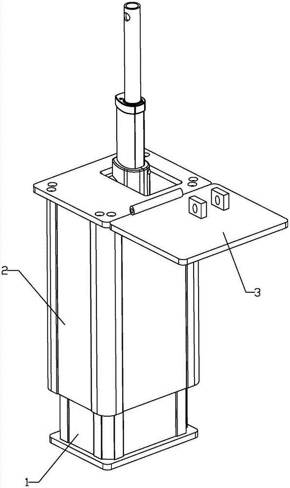
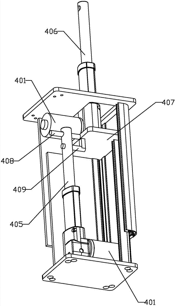
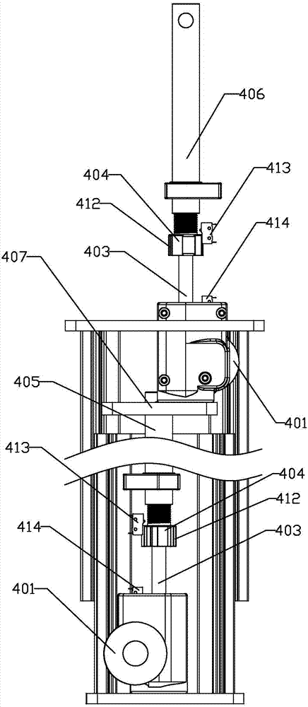
[0027] The present invention will be further described below in conjunction with accompanying drawing, according to Figure 1 to Figure 6 As shown, the multifunctional electric push rod of the present invention mainly includes a mounting base 1, a transmission base 2 and a telescopic transmission assembly. Wherein, the transmission seat 2 is arranged on the installation seat 1 and is slidably connected with the installation seat 1; The telescopic transmission assembly includes a directional transmission mechanism and a direction-changing transmission mechanism. Among them, the directional transmission mechanism is set in the mounting seat 1, which is used to produce a directional telescopic transmission effect on the load on the transmission seat 2; A change in direction produces a steering effect. A flipping part 3 is arranged on the top of the transmission seat 2, and the fixed end of the reversing transmission mechanism is hinged with the transmission seat 2, and the mova...


PUM


Abstract

The invention discloses a multifunctional electric push rod, which comprises a mounting seat, a transmission seat slidingly connected with the mounting seat, and a telescopic transmission assembly is arranged in the cavity formed by the mounting seat and the transmission seat, and is characterized in that: the telescopic transmission assembly It includes the directional transmission mechanism in the installation seat and the direction-changing transmission mechanism in the transmission seat. The upper part of the transmission seat is equipped with a turning part. The fixed end of the direction-changing transmission mechanism is hinged with the transmission seat, and the movable end is hinged with the turning part. . The multifunctional electric push rod of the present invention can realize the adjustable supporting angle of the moving end, has lighting or marking effects, has strong assembly flexibility, and has low processing cost.

Description

technical field [0001] The invention relates to a telescopic linear transmission device driven by electricity, in particular to a multifunctional electric push rod. Background technique [0002] The electric push rod is an electric drive device that converts the rotary motion of the motor shaft into the linear reciprocating motion of the push rod through the change of force. It has high push accuracy, small motion inertia, and can provide a certain degree of weight. Load and other advantages, so it is widely used in various low-load lifting systems, automatic control projection systems, mobile display screens and other occasions. The traditional electric push rod is mainly composed of a fixed seat, a motor, a transmission mechanism and a push rod. It uses the direction-changing effect of the transmission mechanism to convert the rotational motion of the motor into the linear motion of the push rod. However, there are two major technical defects in the current electric push ...

Claims


Application Information

Patent Timeline
Patent Type & Authority Applications(China)
IPC IPC(8): H02K7/06
CPCH02K7/06
Inventor 黄文峰
Owner 佛山市顺德区艾格玛机电科技有限公司
Why Eureka
Try Eureka