
An installation method of a separate synchronous high-voltage motor encoder

A technology of high-voltage motors and synchronous motors, applied in electromechanical devices, manufacturing motor generators, electrical components, etc., can solve problems affecting production output and production efficiency, encoder damage, large excitation current, etc., to improve the complexity of replacement, The effect of improving the service life and shortening the replacement time

Active Publication Date: 2019-06-28
ZHANGJIAGANG POHANG STAINLESS STEEL
View PDF6 Cites 0 Cited by
  • Summary
  • Abstract
  • Description
  • Claims
  • Application Information

AI Technical Summary

Problems solved by technology

[0002] The main motor of the Sendzimir rolling mill adopts a 6000KW 4-pole high-voltage three-phase split synchronous motor, and a total of 6 encoders are installed. The connection method is directly installed on the dummy shaft of the rotor, such as external factors or motor body reasons (by When the oil lift motor lifts the rotor shaft to a certain height), the concentricity deviation is too large, and the left and right shaking is obvious, and the life cycle of the encoder is only about 3 months, which generally leads to low measurement accuracy (the speed fluctuates greatly, especially In the case of low speed), the mechanical position of the rotor is easily lost, the excitation current is too large, which directly affects the production output and production efficiency, and the encoder is seriously damaged.

Method used


Image

  • An installation method of a separate synchronous high-voltage motor encoder
  • An installation method of a separate synchronous high-voltage motor encoder
  • An installation method of a separate synchronous high-voltage motor encoder

Examples


Embodiment Construction

[0023] It should be noted that, in the case of no conflict, the embodiments in the present application and the features in the embodiments can be combined with each other. The present invention will be described in detail below with reference to the accompanying drawings and examples.

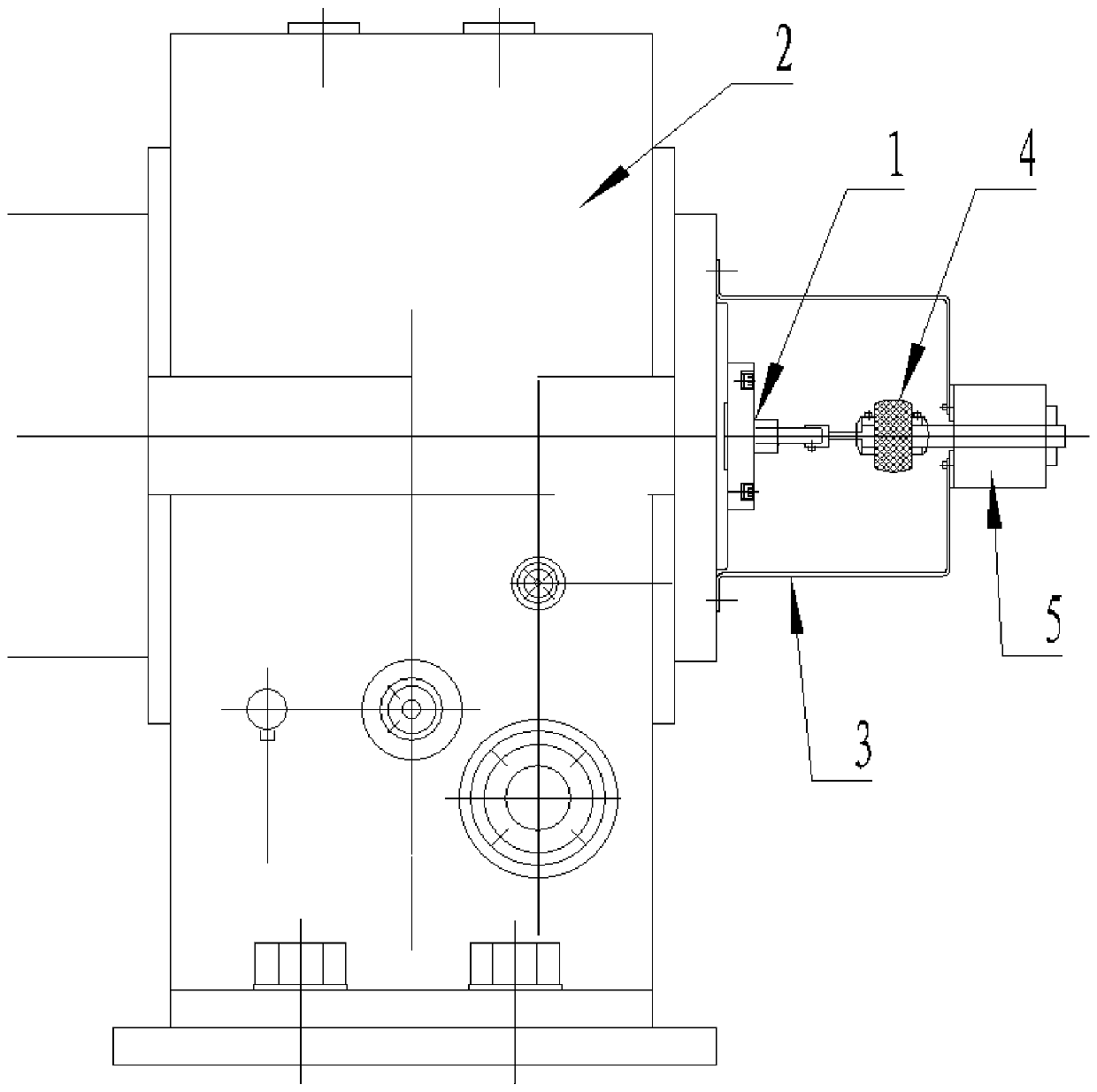
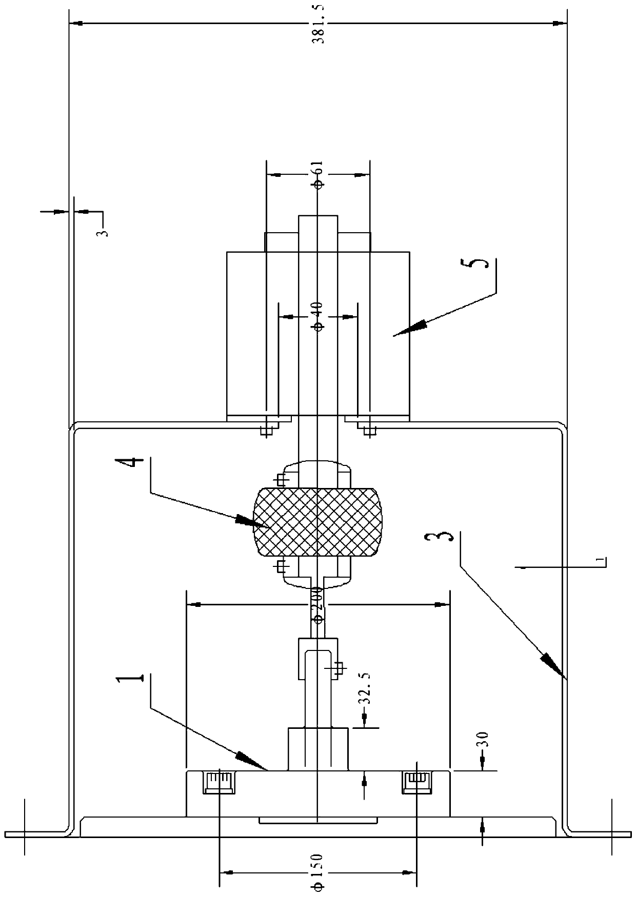
[0024] A method for installing a separate synchronous high-voltage motor encoder, comprising the following steps:

[0025] Step 1. Connect and fix one end of the dummy shaft 1 of the synchronous motor with the main shaft of the motor 2;

[0026] Step 2. Put the encoder end cover 3 on the outside of the dummy shaft 1 of the synchronous motor, so that the encoder end cover 3 and the housing of the motor 2 are initially fixed;

[0027] Step 3. Insert the other end of the dummy shaft 1 of the synchronous motor into one end of the coupling 4 and fix it;

[0028] Step 4. Insert the small shaft of the encoder 5 into the other end of the coupling 4, so that the encoder 5 is connected and fixed with t...


PUM


Abstract

The invention discloses a mounting method of an encoder of a split synchronous high-voltage motor. The mounting method comprises the following steps of 1, connecting a synchronous motor dummy shaft (1) with the motor (2), 2, preliminarily fixing an encoder end cover (3) with a housing of the motor (2), 3, fixing the synchronous motor dummy shaft (1) with a coupler (4), 4, connecting and fixing the encoder (5) with the encoder end cover (3), 5, checking the concentricity of a small shaft of the encoder (5) and the synchronous motor dummy shaft (1), and 6, finally fixing the encoder end cover (3) with the motor (2). The mounting method of the encoder of the split synchronous high-voltage motor eliminates displacement caused by lifting of a rotor spindle, and vertical and horizontal deviations during high-speed operation, greatly reduces the stop time of a production line and purchase of unnecessary spare parts, saves the production cost, and improves the equipment efficiency.

Description

technical field [0001] The invention relates to a method for installing a split-type synchronous high-voltage motor encoder. Background technique [0002] The main motor of the Sendzimir rolling mill adopts a 6000KW 4-pole high-voltage three-phase split synchronous motor, and a total of 6 encoders are installed. The connection method is directly installed on the dummy shaft of the rotor, such as external factors or motor body reasons (by When the oil lift motor lifts the rotor shaft to a certain height), the concentricity deviation is too large, and the left and right shaking is obvious, and the life cycle of the encoder is only about 3 months, which generally leads to low measurement accuracy (the speed fluctuates greatly, especially In the case of low speed), the mechanical position of the rotor is easily lost, the excitation current is too large, which directly affects the production output and production efficiency, and the encoder is seriously damaged and many other pro...

Claims


Application Information

Patent Timeline
Patent Type & Authority Patents(China)
IPC IPC(8): H02K15/00
CPCH02K15/00H02K2213/03
Inventor 王微张民俊石勇飞常晓伟曾志敏陆晓杰周韬
Owner ZHANGJIAGANG POHANG STAINLESS STEEL
Learn More