
Drive device for a motor vehicle

A technology for power equipment and motor vehicles, applied in mechanical equipment, transmission parts, gear lubrication/cooling, etc., can solve problems such as high loss, and achieve the effect of low cost and high operating safety

Active Publication Date: 2017-08-18
AUDI AG
View PDF7 Cites 0 Cited by
  • Summary
  • Abstract
  • Description
  • Claims
  • Application Information

AI Technical Summary

Problems solved by technology

However, this results in a part of the wheel being immersed in the lubricant significantly deeper than the other wheels in this case
This results in relatively high losses due to splash

Method used


Image

  • Drive device for a motor vehicle

Examples


Embodiment Construction

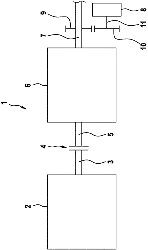
[0042] The drawing shows a schematic illustration of a power plant, for example a component of a motor vehicle which is not shown in detail. The power plant 1 has a power source 2 which is designed, for example, as an internal combustion engine. The drive source 2 has a drive shaft 3 , which is operatively connected or can be operatively connected via a clutch 4 to an input shaft 5 of a transmission 6 . The transmission 6 also has an output shaft 7 which is preferably positively and / or permanently operatively connected to at least one driven shaft (not shown in detail) of the motor vehicle.

[0043] The transmission 6 has a gear set (not shown here) via which the input shaft 5 is operatively connected or can be operatively connected to the output shaft 7 . Different gears or transmission ratios can be provided here between the input shaft 5 and the output shaft 7 by means of the transmission 6 .

[0044] The gear sets of the transmission 6 are supplied with lubricant by mean...


PUM


Abstract

The invention relates to a drive device (1) for a motor vehicle, comprising a drive unit (2) which is or can be operatively connected to an input shaft (5) of a manual transmission (6), wherein a gear set of the manual transmission (6) can be applied with lubricant by means of a primary lubricant pump (8). According to the invention, it is provided that the primary lubricant pump (8) is coupled with an output shaft (7) of the manual transmission.

Description

technical field [0001] The invention relates to a power plant for a motor vehicle having a power source which is or can be operatively connected to an input shaft of a transmission, wherein a gear set of the transmission can be supplied with lubricant by means of a primary lubricant pump. Background technique [0002] The drive unit is used, for example, to provide a drive torque for driving the motor vehicle. The drive unit is preferably a component part of the motor vehicle. The power plant has at least one power source, which is designed, for example, as an internal combustion engine or as an electric machine. The power plant can of course also have several power sources, which in this case are preferably of different types. The first power source is therefore designed as an internal combustion engine, while the second power source is designed as an electric machine. [0003] The power source is operatively connected or can be operatively connected via a transmission t...

Claims


Application Information

Patent Timeline
Patent Type & Authority Applications(China)
IPC IPC(8): F16H57/04
CPCF16H57/0404F16H57/0441F16H57/045F16H57/0456F16H57/0442
Inventor I·格赖特
Owner AUDI AG
Learn More