Suspension assembly for watering cart and use method of suspension assembly

A suspension assembly, sprinkler technology, applied in cleaning methods, road cleaning, construction and other directions, can solve the problem that water flow is easy to splash on the road, cannot adjust the cleaning width of the water spray rack, the deflection angle of the water spray rack, and the flushing effect of the guardrail Incomplete and other problems, to achieve the effect of improving the effect and increasing the cleaning width

Inactive Publication Date: 2017-08-22
HEZHOU SITONG INFORMATION TECH CO LTD
View PDF6 Cites 1 Cited by
  • Summary
  • Abstract
  • Description
  • Claims
  • Application Information

AI Technical Summary

Problems solved by technology

[0004] Dust and dirt will be generated on the surface of the guardrail after long-term use. However, the automatic flushing device disclosed in the above technical solution cannot adjust the cleaning width of the spray rack and the deflection angle of the spray rack. on the road

Method used


Image

  • Suspension assembly for watering cart and use method of suspension assembly
  • Suspension assembly for watering cart and use method of suspension assembly

Examples


Embodiment 1

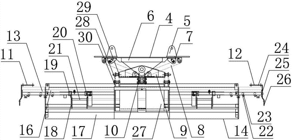
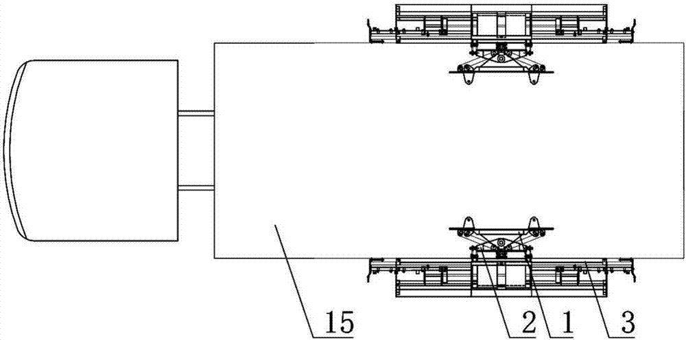
[0028] like figure 1 , figure 2 As shown, the suspension assembly for the sprinkler includes a suspension structure 1, a swing arm structure 2 and a water spray structure 3, the suspension structure 1 includes a suspension bracket 4, and the first lug 5 arranged on the inside of the suspension bracket 4 is set. The suspension shaft 6 outside the suspension bracket 4 is provided with suspension connecting pieces 7 on both sides of the suspension shaft 6; Suspension bracket 7, its other end is connected rocker arm connecting piece 9, and rocking arm connecting piece 7 two ends are provided with lifting terminal, and rocking arm connecting piece 9 outer side is installed transmission gear 10; Mounting seat 12, guide slide rail 13 and water spray support 14, guide slide rail 13 left ends connect vehicle body 15 through left support mounting seat 11, guide slide rail 13 right ends connect vehicle body 15 through right support mount seat 12, guide slide rail 13 is installed Water...

Embodiment 2

[0033] Such as figure 1 , figure 2 As shown, the suspension assembly for the sprinkler includes a suspension structure 1, a swing arm structure 2 and a water spray structure 3, the suspension structure 1 includes a suspension bracket 4, and the first lug 5 arranged on the inside of the suspension bracket 4 is set. The suspension shaft 6 outside the suspension bracket 4 is provided with suspension connecting pieces 7 on both sides of the suspension shaft 6; Suspension bracket 7, its other end is connected rocker arm connecting piece 9, and rocking arm connecting piece 7 two ends are provided with lifting terminal, and rocking arm connecting piece 9 outer side is installed transmission gear 10; Mounting seat 12, guide slide rail 13 and water spray support 14, guide slide rail 13 left ends connect vehicle body 15 through left support mounting seat 11, guide slide rail 13 right ends connect vehicle body 15 through right support mount seat 12, guide slide rail 13 is installed Wa...


PUM


Abstract

The invention discloses a suspension assembly for a sprinkler, relates to automobile technology, and is used to solve the problem that the existing automatic flushing device cannot adjust the cleaning width of the spray frame and the deflection angle of the spray frame, the cleaning effect of the protective fence is not thorough, and the water flow Problems with easy splashes on the road. It includes a suspension structure, a swing arm structure and a water spray structure. The suspension structure includes a suspension bracket, a first lug arranged inside the suspension bracket, a suspension shaft arranged outside the suspension bracket, and suspension shafts on both sides of the suspension shaft. Connecting piece. This technical solution can adjust the cleaning width of the water spray frame and the deflection angle of the water spray frame. High-pressure cleaning of road shoulders and guardrails or flushing and watering of roadside green belts. The invention also discloses a method for using the suspension assembly for the sprinkler.

Description

technical field [0001] The invention relates to automobile technology, in particular, to a suspension assembly for a sprinkler and a method of use thereof. Background technique [0002] Sprinklers are also known as sprinklers, multi-functional sprinklers, landscaping sprinklers, water tankers, and water trucks. The sprinkler is suitable for washing various road surfaces, trees, green belts, lawn greening, construction of roads, factories and mines, and high-altitude building washing. The existing sprinkler has the function of flushing the guardrail. [0003] Patent document 200810057997.9 discloses an automatic flushing device for the isolation pier of the road guardrail, which consists of a small cylinder, a large cylinder, a stop valve, a water inlet pipe, a flexible water pipe, an adjustment bracket, a cantilever, a connecting plate, a return spring, a lifting frame, and a water spray pipe The lifting frame is composed of a top beam and a support rod, and the top beam i...

Claims


Application Information

Patent Timeline
Patent Type & Authority Applications(China)
IPC IPC(8): E01H3/02
CPCE01H3/02
Inventor 刘有萍杨焱
Owner HEZHOU SITONG INFORMATION TECH CO LTD
Why Eureka
Try Eureka